(reposted from here thx to a comment by Matt_C)
I would need help of an expert, familiar with the Black Cube.
I’m in the course of building/designing a Cube carrier board, and have a scheme which I believe is fully working. However, I observe two points which I just can’t figure out. I would much appreciate input as regards these points.
FIRST SOME BACKGROUND (a bit lengthy):
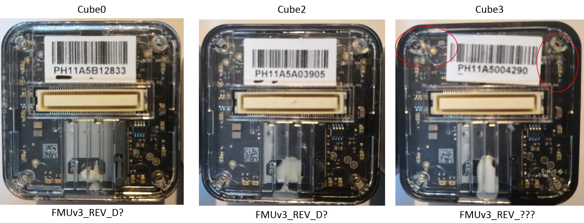
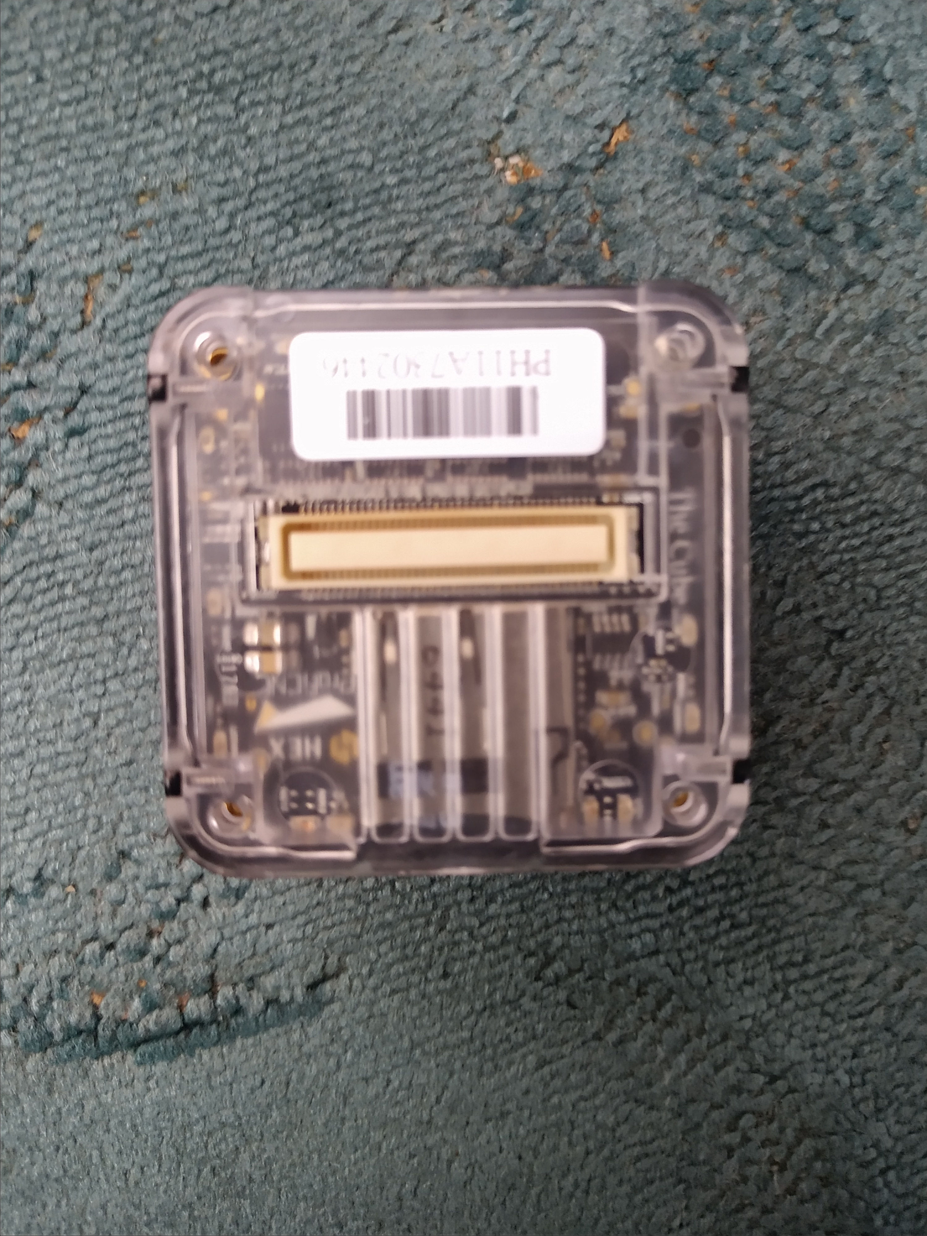
I have three Cubes for my tests, which I will call Cube0, Cube2, and Cube3:
picture1 in next post since as a new user I’m not allowed to post more than one
Cube0 and Cube2 appear to be identical hardware-wise, and their visible PCB matches FMUv3_REV_D. Cube3 however is a different hardware revision. It neither matches FMUv3_REV_D, FMUv3_REV_G, nor FMUv3_REV_1B. From the serial number one might conclude it’s an earlier revision than Cube0 and Cube2.
In order to establish a comparable test situation I have flashed all three cubes first with ArduPlane to wipe out the parameters, then flashed them with ArduCopter 3.6.7 (or BetaCopter but this doesn’t matter here), and set “my default” parameters by loading one and the same .param file into MissionPlanner and writing the params to the cubes. I use the Nuttx v3 firmware versions (ArduCopter-v3.px4).
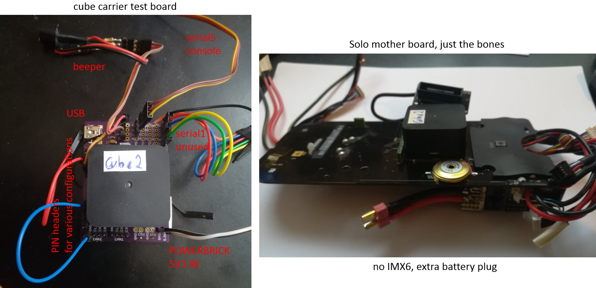
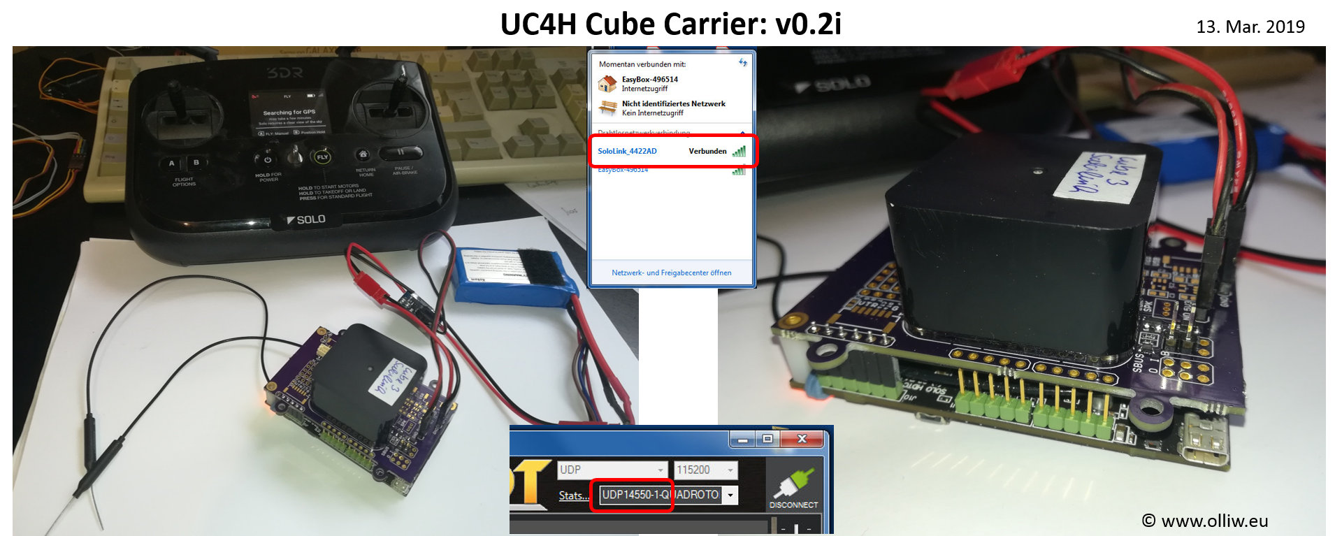
I have two test environments, first my home-made cube test carrier board and second a Solo motherboard with the IMX6 removed and a battery plug for powering:
picture2 in 2nd-next post since as a new user I’m not allowed to post more than one
On the Cube test carrier board I can power the Cube from a 5V3 powerbrick source or from the USB plug. I also have connected the PC to the Serial5 debug console to see what’s going on. I can change some things by use of some pin headers.
I have waded through what I believe are all publicly available electrical schemes for the Cube (FMU), PSM, and CB, as well as through the relevant pieces of code in AP and the bootloader.
The result of my research into the electrical schemes and codes is that only the connections VDD-5V-IN-PROT and VBUS on the cube’s 80-pin header (and of course GND) are relevant for the following. All other ‘power-related’ pins, VDD-SERVO, VDD-SERVO-IN, IO-VDD-3V3, VDD-3V3-SPEKT-EN, VDD-5V-PERIPH-EN, VDD-BRICK-VALID, VDD-BACKUP-VALID, VBUS-VALID, VDD-5V-PERIPH-OC, and VDD-5V-HIPOWER-OC, are irrelevant for the following (for different reasons, but irrelevant).
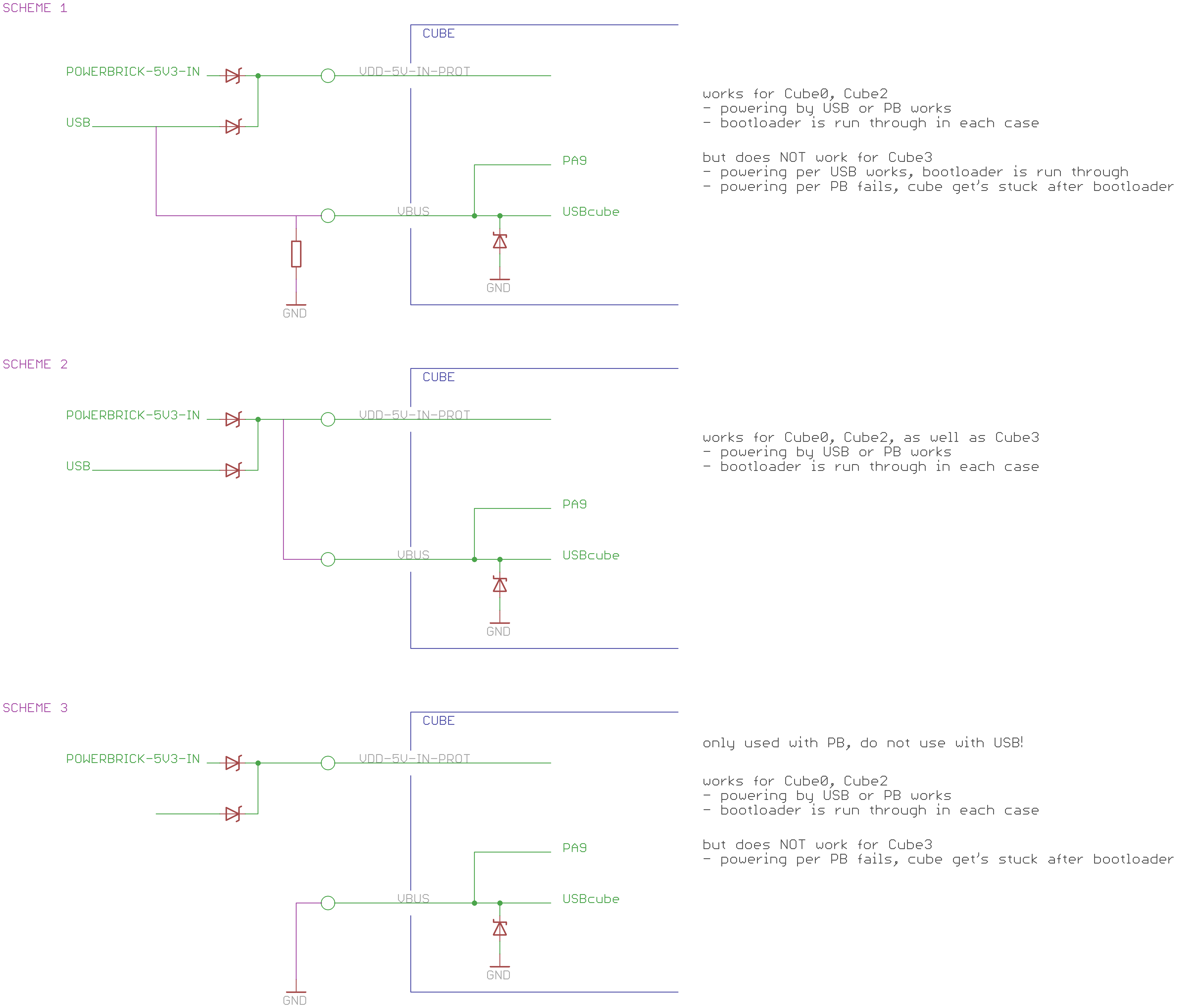
The VDD-5V-IN-PROT is the Cube’s main 5V power supply. VBUS is connected to the Cube’s internal USB plug, protected by a Z-diode, and connected to the PA9 VBUS pin of the STM32F437. This is the part is encircled by the blue line in the scheme drawing below.
The PA9 VBUS pin is used in the ArduPilot code, but also in the bootloader: It’s state is read and if high the bootloader jumps directly to the app, and if low the bootloader waits 5 secs before it jumps to the app:
THE TESTS:
Four test conditions will be considered:
A) Cube test carrier with Scheme2
B) Cube test carrier with Scheme1
C) Solo motherboard
D) Cube test carrier with Scheme3
The three schemes are these:
picture3 in 3rd-next post since as a new user I’m not allowed to post more than one
THE OBSERVATIONS:
The following deals with what happens after powering up the cube/system. The chain of events can be broadly distinguished into two phases:
- bootloader delay phase: The bootloader waits for 5 secs for some activity on the USB before it jumps to the app. The Cube’s orange LEDs blink quickly. If a USB is connected the USB is enumerated and de-enumerated (the PC’s soundspeaker pings twice).
- AP initialization: The app starts. The Cube’s LEDs flicker and eventially go off. Debug messages are send to Serial5. The beeper makes noises. If a USB is connected it is enumerated by the PC. It is possible to connect with MissionPlanner to the Cube. And so on and forth.
Observations for test condition A:
Everything works fine. All three cubes undergo the bootloader delay phase, start up and behave just fine.
Observations for test condition B:
Here the behavior is very different for Cube0/Cube2 and Cube3.
For Cube0/Cube2 everything works fine. Both cubes undergo the bootloader delay phase, start up and behave just fine, irrespective on how they are powered, through the 5V3 powerbrick or the USB.
However, Cube3 undergoes the bootloader delay phase, starts up and behaves just fine ONLY if powered by the USB! If powered from the 5V3 powerbrick it undergoes the bootloader delay phase, but then gets stuck and does NOT jump to the AP initialization! The orange LEDs are then on constantly, and the Cube appears to be just “dead”. There is absolutely NO output on the debug console Serial5, so the AP initialization phase wasn’t even started.
Note that the electric connections in Scheme2 are supposed to mimic the original PSM, which instead of the diode OR-ing has a power switch, but otherwise I can’t see any electrically relevant difference.
Note also that the problem exists for only Cube3, which appears to be an earlier hardware revision than Cube0&Cube2.
Observations for test condition C:
Everythings works fine. All three cubes start up and behave just fine.
However: The cubes do NOT undergo the bootloader delay phase! Instead they are only briefly in the bootloader and then jump directly to the app i.e. AP initialization.
Observations for test condition D:
In the Scheme3 used here the VBUS line and therefore the voltage at PA9 is forced to low by connecting it to ground (accordingly here the system must not be powered by USB but just from the powerbrick).
The behavior is exactly as that for test condition B, when powered from the 5V3 powerbrick. Cube0/Cube2 just work fine. Cube3 undergoes the bootloader delay phase, but then gets stuck and does not jump to the app.
THE QUESTIONS:
There are two questions from the above, first why Cube3 behaves differently to Cube0/Cube2, and second why the bootloader delay phase is not skipped except when using the Solo motherboard.
Why does Cube3 behave differently to Cube0/Cube2?
The only difference I can see between ‘powered by USB’ and ‘powered by the powerbrick’ is the voltage on PA9. So I think the question can also be stated as: Why does Cube3 not start the AP app when PA9 is low, but gets stuck and fails to start?
Note that the difference of Scheme1 as compared to Scheme2 is that it forces PA9 to high in all conditions, which seems to confirm the conclusion that it’s the voltage level on PA9 which is relevant.
It is strange though that Cube3 behaves just fine on the Solo motherboard. As mentioned, Scheme1 used in test condition B is supposed to mimic the PSM used on the Solo motherboard. So the question is actually twofold: Why doesn’t Scheme1 work for Cube3 and what is so magic about the Solo motherboard/PSM that it here works?
Why is the bootloader delay phase not skipped except when using the Solo motherboard?
This observation, that the bootloader delay phase is skipped with the Solo motherboard, really caught me by surprise. I’ve not observed that for all my other boards (pixracer, AUAVX2, Pixhawk1). They all undergo the bootloader delay phase, and this so even though their electrical schemes are identical in that here too PA9 is connected to VBUS. Test condition D appears top confirm this, i.e. that the bootloader delay phase is undergone independent on the voltage level on PA9.
This however is appears to be in contradiction with the bootloader code. And it raises the question what is so magic about the Solo motherboard/PSM that here the bootloader delay phase is skipped?
If you made it to here you really deserve my deepest thanks 
Cheers, Olli