Hi,
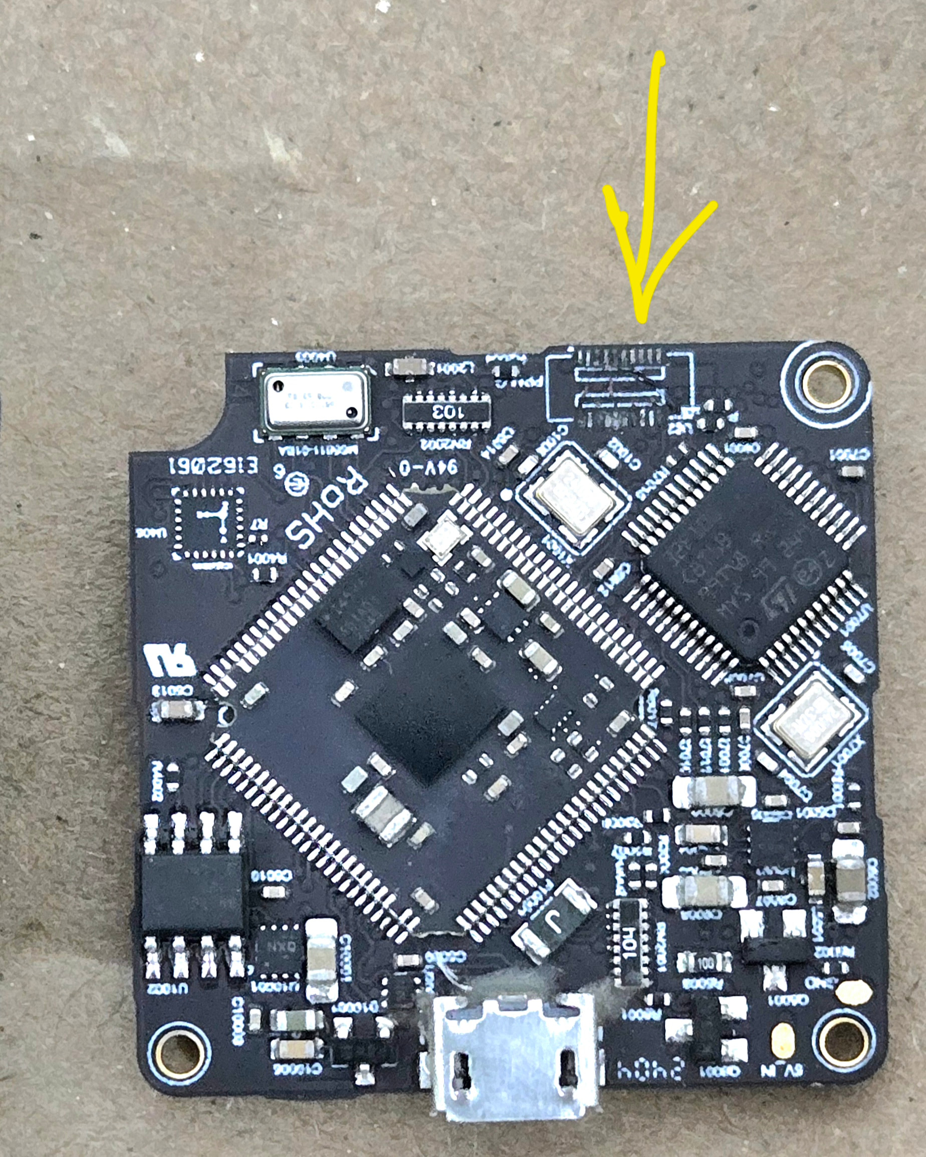
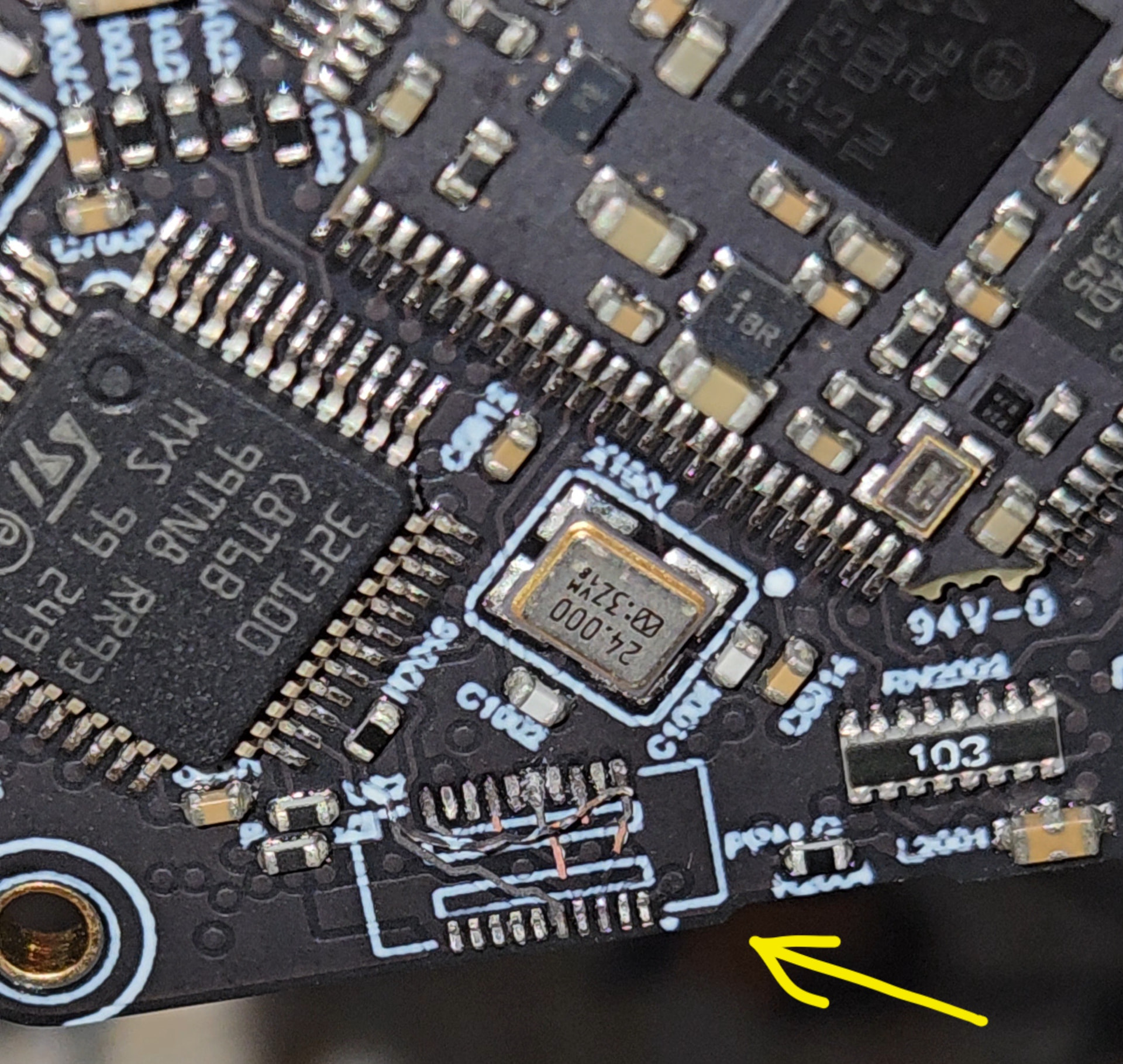
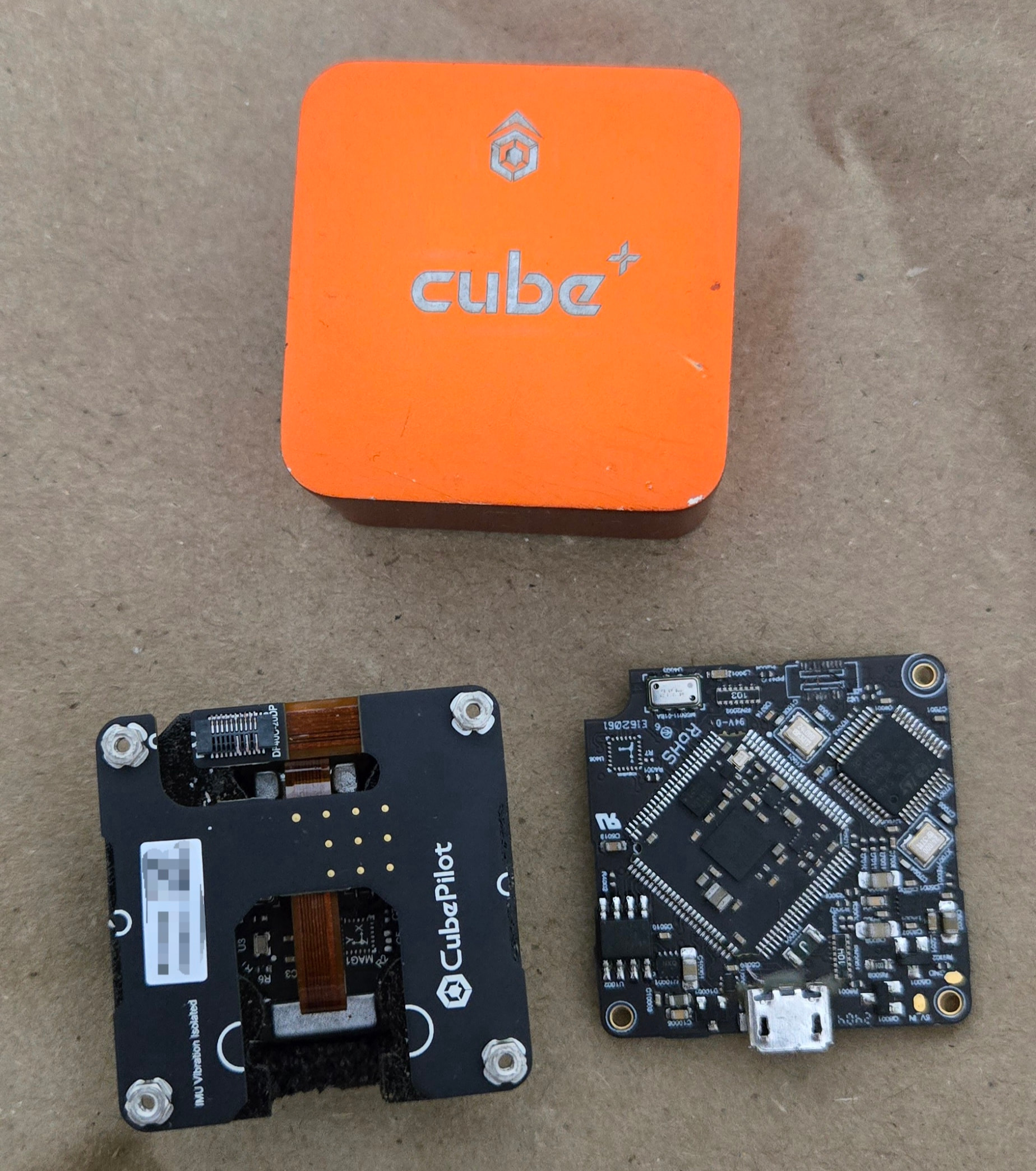
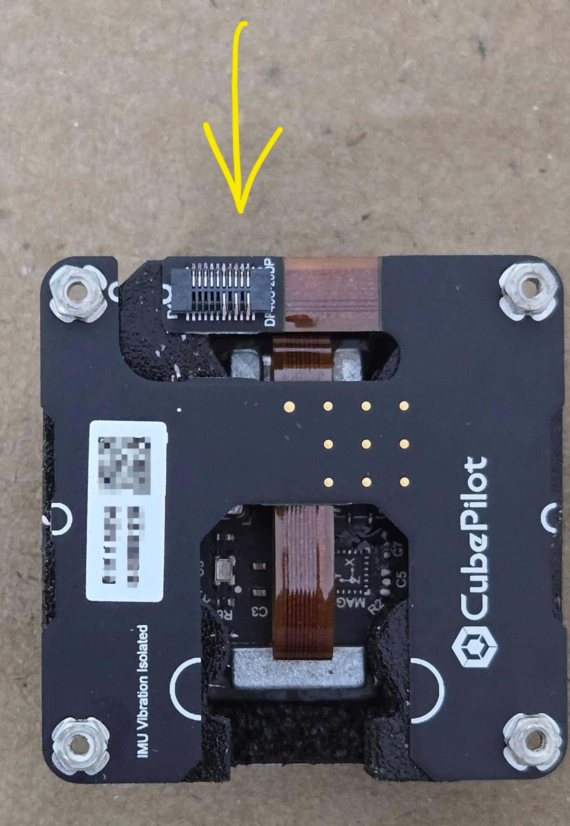
I have a Cube Orange+ that I am trying to repair at the hardware level. The board-to-board IMU connector was damaged, and some PCB pads/traces were pulled off together with the connector.
I want to repair the damaged connections and restore the full IMU redundancy.
While investigating, I found the older “IMU For The CUBE – IMU Rev 1A (2018)” schematic in the ProfiCNC GitHub repository, which shows the DF40C-20 connector and IMU connections.
However, my Cube Orange+ is a 2024 unit, and I believe it uses the later IMU Rev 3 design. I have not been able to find the Rev 3 schematic or connector pinout.
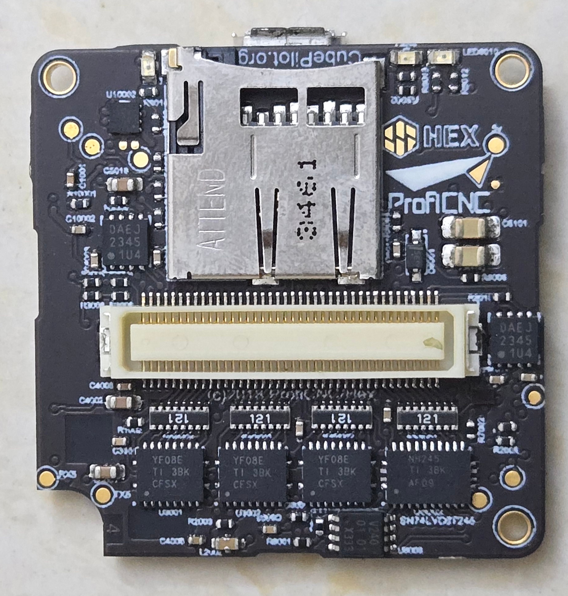
I have attached photos showing the damaged connector/PCB.
Could anyone confirm whether the older IMU Rev 1A schematic applies to the Orange+, or provide the IMU Rev 3 connector pinout/signal mapping?
Even just the DF40C connector pinout and the corresponding power, GND, SPI/I²C and IMU signal connections would be extremely helpful. This would allow a microsoldering technician to reconstruct the connections where the pads/traces were torn off.
If the complete schematic cannot be shared, a connector pinout or documentation showing the differences between IMU Rev 1A and Orange+ IMU Rev 3 would be greatly appreciated.
Thanks!