Cube Orange: MAVLINK over GPS2 port problems

Hi,

first of all I am new to this so please be gentle with me :wink:

Secondly what I would like to achieve is to transfer MAVLINK data between Cube Orange and my PC over Microhard pMDDL2450 radio module.

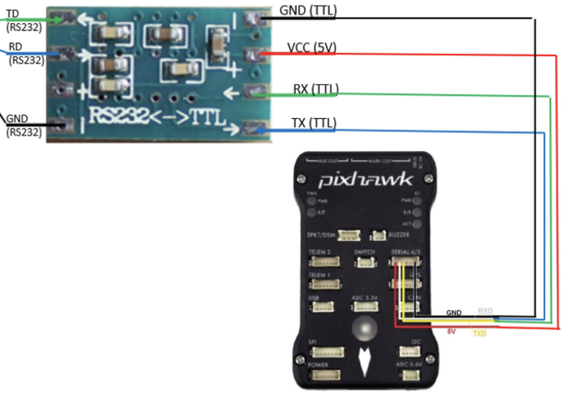
I have managed to configure radio modules for serial transfer so with this I have no problems. I am aware that Cube serial is TTL level and Microhard is RS232 level so I am using RS232/TTL shifter in between. This connection is working as I connected a GPS module with TTL output directly (trough RS232/TTL shifter of coarse) to Microhard radio serial and I get the data on the other end (with Microhand connected to PC over USB to Serial adapter).

The problem is I canā€™t seem to get the data from Cube Orange GPS2 serial port (or any other serial port besides serial0 (USB)).

So first of all I would like to clarify if I made the correct connection. All I could find about port pinouts was this site: https://ardupilot.org/copter/docs/common-pixhawk-overview.html. So I used this section as if understand correctly GPS2 is on serial4:

SERIAL 4/5 port - due to space constraints two ports are on one connector.

| Pin | Signal | Volt |

| 1 (red) | VCC | +5V |
| 2 (blk) | TX (#4) | +3.3V |
| 3 (blk) |RX (#4) | +3.3V |
| 4 (blk) | TX (#5) | +3.3V |
| 5 (blk) | RX (#5) | +3.3V |
| 6 (blk) | GND |GND|

With connected TX, RX and GND.

Next I connected Cube to PC over USB cable and opened Mission Planner (MP) to set the serial for MAVLINK. So Iā€™ve set SERIAL4_BAUD 57, SERIAL4_OPTIONS 0 and SERIAL4_PROTOCOL 1. Then I also set the SRn parameters (I copied what was in SR0 to all the others as I know serial0 is working fine and I get data form it). I know how SR parameters are working regarding serial interface, but as I was experimenting with different serial ports I set them all to SR0 values. Now as far as I am concerned this should be all I need to do or am I missing something?

Next thing I did was to connect the Cube to PC over TTL to USB adapter (which I first checked with previously mentioned GPS to confirm it is working) to see if I get any data out. Opened the serial port with Hercules Setup Utility to see if I have any data flowing in. And I have no data coming over to my PC (If I connect to MAVLINK port with Hercules I get data out so it should work). Then I tried to connect to same port with MP and had no luck also.

As I didnā€™t get any data out I tried swapping RX/TX pins. Both physical and later with SERIAL_OPTIONS. I tried setting RX/TX PullUp. Nothing resolved the issue.

Also tried everything with GPS port (serial3) as I connected GPS to it and I know the port is working.

And this is where I am stuck. So my questions are:

  • is the pinout used correct?
  • are the settings OK or do I need to enable anything else?
  • do I maybe need to initiate MAVLINK data stream with some command (what I learned in the process setting SR parameters should do that, but I might be wrong)?
  • I am wright to assume I can connect to Cube with MP over other serial ports, besides serial0?
  • what else can I try? Any guidance would be helpful.
  • what am I missing?

Mission Planner version used: 1.3.72 build 1.3.7463.24854
Cube firmware: ArduCopter V4.0.3 (ffd08628)

Thank you all in advance.

You may check the pinout from here: https://github.com/ArduPilot/ardupilot/tree/51e187342b40cf4b1f0149daaf3eedd9dc9726bb/libraries/AP_HAL_ChibiOS/hwdef/CubeBlack

The ports are the same except serial 5 is reserved for ADSB on ADSB carrier boards.

SERIAL 4/5 ports are not on the same connector. You may have a look at the GPS2 pinout

As far as I know you donā€™t need to set SERIAL_OPTIONS in your purpose.
Why do you need to connect to MP through serial 4? Why not use the usb extender cable?

1 Like

HI Alvin,

thank you for your response. From the link provided I see that the first portion of GPS2 port is the same. So serial 4 pinout should work for me as it is. SERIAL_OPTION was changed only to see if it makes any difference. My first thought was also that there is no need to change options. Connecting to MP through serial 4 is just for testing, to see whether it is working or not. I was just wondering if I connect one radio module to Cube and the other to PC if I can then connect to Cube in MP over the radio module. Is this possible or is connecting to MP limited to serial 0 port.

Anyway I will try switching to TELEM2 port to see if I get any luck.

OK. Got this setup working now.

TL;DR: It was a hardware problem. RS232 to TTL level shifter was to blame.

I first tried TELEM2 port and had no luck. Then I decided to look the output signal of Cube on oscilloscope and there was indeed some traffic. Checked the RS232/TTL to USB and noticed that there was a 5V on TTL port. Looking at pinout it should be 3.3V. So I changed connection from Cube to RS232/TTL to USB from TTL port to RS232 port, with MAX232 (RS232 to TTL) chip in between. First powered the MAX chip with external 3.3V and it worked. Got the data flowing to my PC. Next I tried powering MAX chip with 5V from Cube. Also worked as it should. So there was a hardware problem. Probably pull-up was to strong at TTL to USB translator.

Then I tried the same for GPS2 port and it also worked :slight_smile:

And to answer my own questions:

  • pinout used for serial 4 is correct
  • settings that needs to be set are SERIAL4_BAUD xx, SERIAL4_PROTOCOL 1 and appropriate SR parameters.
  • no need to initiate MAVLINK data stream with some command. Setting SR parameters will do the job.
  • I can connect to Cube with MP over other serial ports. If correctly set I can connect even through radio module (baud rate must be set at the same speed).

What I also learned in the process is that swap pin on TELEM2 port doesnā€™t work on my Cube. Also INVERT_RX. Didnā€™t check other ports so I have no clue whether it works there or not. And also after parameters are changed and written to Cube one has to restart the Cube in order the changes are applied.

Hi @Nadskof ,
It looks like Iā€™m working on a project that is similar to yours. Iā€™m trying to use a telemetry datalink that outputs a RS232 signal (in the copter). The RS232 signal consists of MavLink messages. The RS232 signal has a baud rate of 115200. Iā€™m wondering if itā€™s possible to convert the RS232 signal to TTL using a simple converter like this one: MAX3232 Mini RS232 naar TTL converter - Opencircuit . Please refer to the wiring diagram below.


With your experience, do you think this is possible? And/or am I missing something important?
Thanks in advance!

PS Iā€™m planning to set these parameters for the Cube Orange:
SERIALx_BAUD 115200
SERIALx_OPTION 0
SERIALx_PROTOCOL 2

1 Like

Hi Max,

from my experience it will work with simple converter like this. I used a similar one at start. The problem is it will not last long. At high baud rate they tend to get vary hot and will stop working. One time it got so hot MAX3232 chip got de-soldered and fell of the PCB. Didnā€™t try how it works if heatsink is attached as we made custom PCB to handle level shifting.

As for the schematics I canā€™t see clearly which goes where, but if I see correctly you have TX and RX switched. As far as I know pin 2 on pixhawk is TX and if I remember correctly it should connect to RX (arrow in) on level shifter. On your schematics pin 2 is labelled as RX.

Parameters for cube seems ok, but donā€™t forget to set the SRx parameter to get the MavLink data flow on selected serial.

Best regards

1 Like

Hi @Nadskof ,

Thanks for the detailed response!

Itā€™s good to know that the chip cannot handle high baud rates. Do you think that the MAX3232 chip can withstand a baud rate of 57600? (In that case I obviously have to set the SERIALx_BAUD to 57600.)

A custom PCB is a very clever solution. Did you still use the MAX3232 chip or did you completely design it with logic ports or other chips?

I will have to do some more research on the SR-parameters. I normally donā€™t touch them and keep it as default.

Above you talked about a problem with the RS232 to TTL converter. Was it just a broken RS232 to TTL converter?

Thanks in advance!

Hi Max,

we still used MAX3232 chip. They can handle high baud rate, just not on cheap PCBs. I think they will go up to 230400 bauds according to datasheet. I was not the one to design the PCB so I canā€™t help you with that. But I recon if you stick some heatsink on the chip it will help with overheating.

In my case there was a problem with ā€œbrokenā€ RS232 to TTL converter. It was actually a combined RS232 to USB and TTL to USB converter and in my mind I thought it also works as RS232 to TTL. When that was figured out I switched on using TTL to USB conversion. That setup still didnā€™t work for me as the voltage for logic 0 on TTL side didnā€™t drop low enough to be treated as 0. Probably to strong pull-up resistor. Than I switched to low cost RS232 to TTL converter similar to one you mentioned and it worked. But with already mentioned problems.

Best regards

Hi @Nadskof,

Good to know that you also used the MAX3232 chip on the custom PCB. That chip should work fine for my project too.

Thanks for the more detailed information about your first problem with another chip. Itā€™s all clear to me.

Kind regards,
Max

Hello,

Can you brief me a bit about the SRx parameter?