I am running AP_Periph on the head of master on a CubeNode, which is setup to communicate GPS Fix messages over DroneCAN at 1Mb/s on CAN1. Additionally, I have SLCAN enabled on the OTG interface allowing me to connect via the DroneCAN GUI over serial.
The issue I am seeing is that, while I see all messages intending to be sent properly on the SLCAN interface, messages are not actually appearing on the actual CAN bus in full when viewed from a separate socketcan interface tied into the bus directly.
After some detailed investigation, it appears that the STM32H757xx has a configured hw tx buffer size of 7 frames, and the CubeNode is only able to send 7 frames of data out at once when several messages (of the same or different multiframe type) are queued in quick succession.
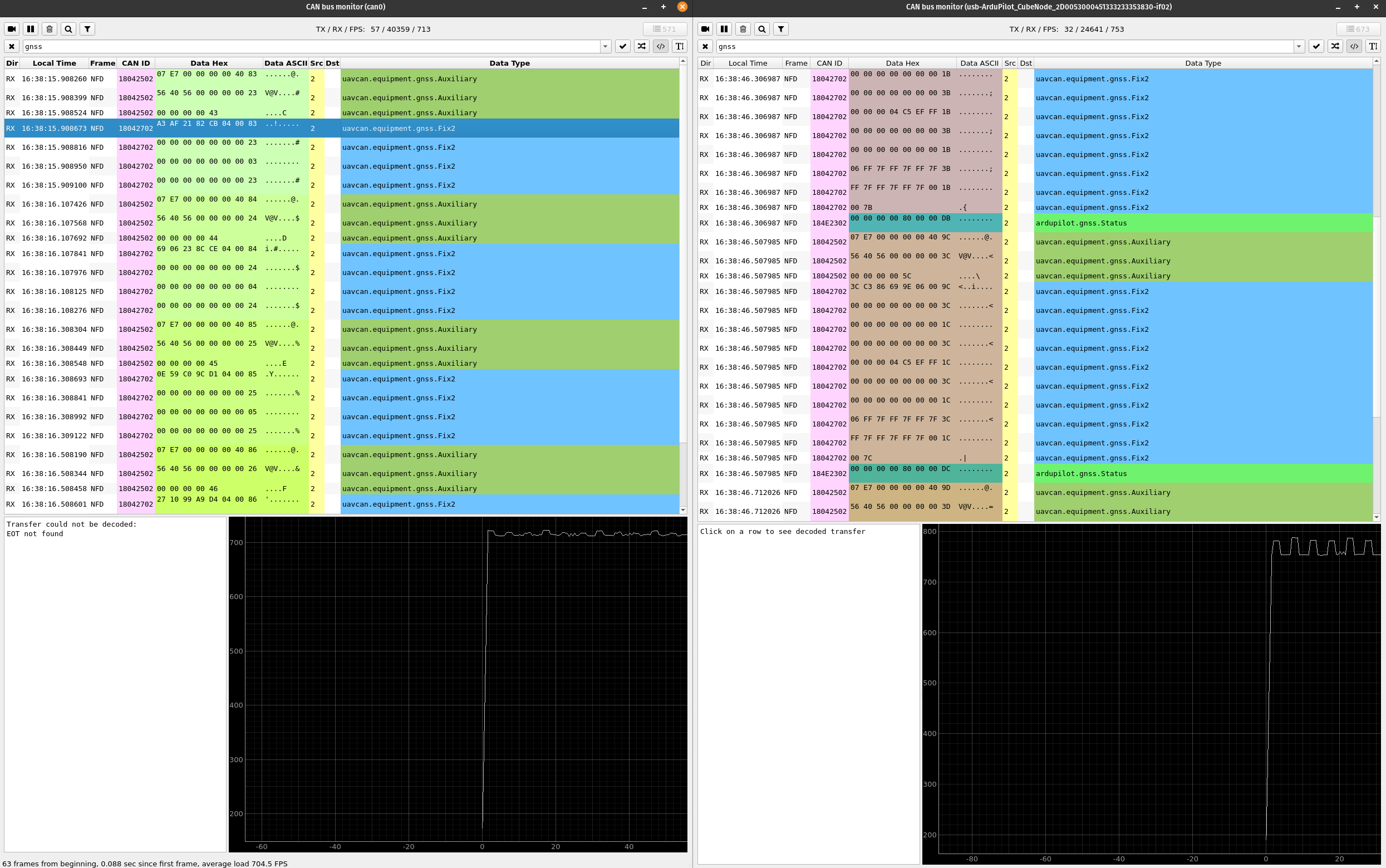
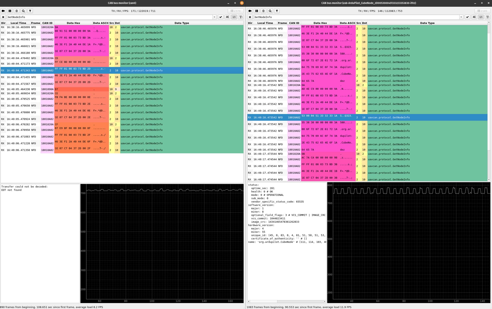
Here is an image of the gnss messages that are intending to be sent at 5Hz on the bus. The left side is the SocketCAN bus monitor, and the right side is the SLCAN bus monitor on the CubeNode. This is not isolated to gnss messages either, I see similar behavior on the GetNodeInfo message types.
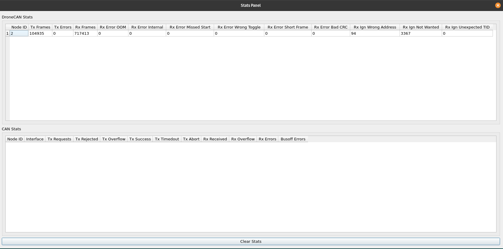
Enabling the CAN stats also shows zero cause for concern, and after reading the code, it seems like drops this severe should be incrementing either the tx errors field. There are also no error frames on the bus when viewed over socketcan. A different SLCAN interface on a CubeOrange on the same bus shows exactly what the socketcan interface does as well. The bus itself also looks healthy on an oscillocope and is properly terminated / topology is in order.
I am suspecting at this point that there is a bug within the AP Periph firmware as I am struggling to find any reason otherwise, but given where the implementation is at today it appears like this has been shown to work by others.
Any ideas / help / confirmation on any of the above would be much apperciated as I feel I’ve exhausted my custom firmware tweaks at this point to try and get this working.
Here is the hwdef.dat file I’ve altered from master to enable the avrious additional features
hwdef.dat
# hw definition file for processing by chibios_hwdef.py
# for H757

# MCU class and specific type
MCU STM32H7xx STM32H757xx
MCU_CLOCKRATE_MHZ 480

define CORE_CM7
define SMPS_PWR

# board ID. See Tools/AP_Bootloader/board_types.txt
APJ_BOARD_ID AP_HW_CUBENODE

# setup build for a peripheral firmware
env AP_PERIPH 1
define HAL_LOGGING_ENABLED 1

FLASH_SIZE_KB 2048

# the location where the bootloader will put the firmware
# the H757 has 128k sectors, assign 2 sectors for BL
FLASH_BOOTLOADER_LOAD_KB 256
FLASH_RESERVE_START_KB 256

# crystal frequency
OSCILLATOR_HZ 24000000

# CAN1
PD0 CAN1_RX CAN1
PD1 CAN1_TX CAN1

# CAN2
PB5    CAN2_RX    CAN2
PB6    CAN2_TX    CAN2

# CAN Common
define HAL_ENABLE_SENDING_STATS 1
define HAL_CAN_POOL_SIZE 32000
PG1 SLEEPCAN OUTPUT PUSHPULL SPEED_LOW LOW
PG0 SHUTDOWNCAN OUTPUT PUSHPULL SPEED_LOW LOW

# SERIAL
# define AP_PERIPH_SERIAL_OPTIONS_ENABLED 1

# USB
PA11    OTG_FS_DM    OTG1
PA12    OTG_FS_DP    OTG1

## GPS1?
PE0 UART8_RX UART8
PE1 UART8_TX UART8
# based on SERIAL_ORDER, zero indexed
define HAL_PERIPH_GPS1_PORT_DEFAULT 1

## GPS2?
PE7 UART7_RX UART7
PE8 UART7_TX UART7
# based on SERIAL_ORDER, zero indexed
define HAL_PERIPH_GPS2_PORT_DEFAULT 2

## default the 2nd interface to SLCAN
define HAL_OTG2_PROTOCOL SerialProtocol_SLCAN

## order of UARTs (and USB)
SERIAL_ORDER OTG1 UART8 UART7 OTG2


# GPIOs
## Number of PWMs
#define HAL_PWM_COUNT 4
### Estop PWM OUT
#PE14 TIM1_CH4 TIM1 PWM(1) GPIO(50)
### Charger PWM OUT
#PE13 TIM1_CH3 TIM1 PWM(2) GPIO(51)
### Estop PWM IN
#PD13 TIM4_CH2 TIM4 PWM(3) GPIO(54)
### Charger PWM IN
#PD14 TIM4_CH3 TIM4 PWM(4) GPIO(55)

## enable estop and charger detection via AP_BUTTON
## Need to set several BTN_x parameters to use this
#define HAL_BUTTON_ENABLED 1
## enable RC_Channel library, needed for AP_BUTTON
#define AP_RC_CHANNEL_ENABLED 1
## disable RSSI, breaks the build
#define AP_RSSI_ENABLED 0

# These are the pins for SWD debugging with a STlinkv2 or black-magic probe.
PA13 JTMS-SWDIO SWD
PA14 JTCK-SWCLK SWD

# override following defines as needed
define HAL_USE_ADC FALSE
STORAGE_FLASH_PAGE 14
define HAL_STORAGE_SIZE 32768

# Ethernet
# PC1  ETH_MDC            ETH1
# PA2  ETH_MDIO           ETH1
# PC4  ETH_RMII_RXD0      ETH1
# PC5  ETH_RMII_RXD1      ETH1
# PB12 ETH_RMII_TXD0      ETH1
# PB13 ETH_RMII_TXD1      ETH1
# PB11 ETH_RMII_TX_EN     ETH1
# PA7  ETH_RMII_CRS_DV    ETH1
# PA1  ETH_RMII_REF_CLK   ETH1

define BOARD_PHY_ID  MII_LAN8720_ID
define BOARD_PHY_RMII
#define AP_PERIPH_NETWORKING_ENABLED 1

# IMU
PC10 SPI3_SCK SPI3
PC11 SPI3_MISO SPI3
PC12 SPI3_MOSI SPI3
PG15 IMU_CS CS

SPIDEV icm45686  SPI3  DEVID4  IMU_CS   MODE0  24*MHZ  24*MHZ

IMU Invensensev3 SPI:icm45686 ROTATION_NONE

define AP_PERIPH_IMU_ENABLED 1

# Periph GCS
define HAL_GCS_ENABLED 1

#################################
# AP_Periph - configurations specific to this App
#################################

define HAL_BARO_ALLOW_INIT_NO_BARO
define AP_CAN_SLCAN_ENABLED 1
define AP_PERIPH_BATTERY_ENABLED 1
define AP_PERIPH_GPS_ENABLED 1
define AP_PERIPH_MAG_ENABLED 1
define AP_PERIPH_BARO_ENABLED 1
define AP_PERIPH_RC_OUT_ENABLED 1
define AP_PERIPH_NOTIFY_ENABLED 1
define AP_PERIPH_IMU_ENABLED 1

# GPS and compass configured to handle moving baseline
define GPS_MAX_RECEIVERS 2
define GPS_MAX_INSTANCES 2
define HAL_COMPASS_MAX_SENSORS 1
define GPS_MOVING_BASELINE 1
define AP_GPS_UBLOX_ENABLED 1

define HAL_NUM_CAN_IFACES 2
define HAL_CAN_DRIVER_DEFAULT 1

# define AP_NETWORKING_MAX_INSTANCES 4

# define AP_SCRIPTING_ENABLED 1
define AP_FILESYSTEM_ROMFS_ENABLED 1

# listen for reboot command from uploader.py script
# undefine to disable. Use -1 to allow on all ports, otherwise serial number index defined in SERIAL_ORDER starting at 0
define HAL_PERIPH_LISTEN_FOR_SERIAL_UART_REBOOT_CMD_PORT 0
#################################

define HAL_MONITOR_THREAD_ENABLED 1
define HAL_SCHEDULER_ENABLED 1