PSM section as per original design is present on the board but is not assembled. I have bypassed this section fully since this is custom design. Rest of the schematics are exactly same including values and MPN. (Except for passives)
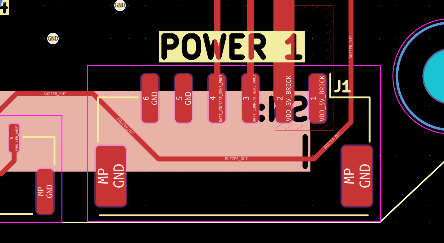
This carrier board (CB) had the requirement for providing on board 5.3V supply omitting the need for a separate BEC. So this CB takes in a direct 12S connection and has a switching DCDC converter to produce the 5.3V and is connected to the net VDD_5V_BRICK (POWER1 net as per sch). As mentioned since the PSM section is bypassed and so VDD_5V_BRICK, VDD_5V_BACKUP and VBUS to shorted to VDD_5V_IN_PROT.
The issue: When the Cube is connected and power is supplied to the board, I don’t see any LED indication from the Orange Cube.
Directly on the pins of the DF17 connector for the cube I can measure the following:
What am I missing? Please let me know if I have missed any signals that needs to be also bypassed. Please also note that the BEC is not connected to POWER1 or POWER2. So BATT_CURRENT_SENS_PROT and BATT_VOLTAGE_SENS_PROT is left floating.
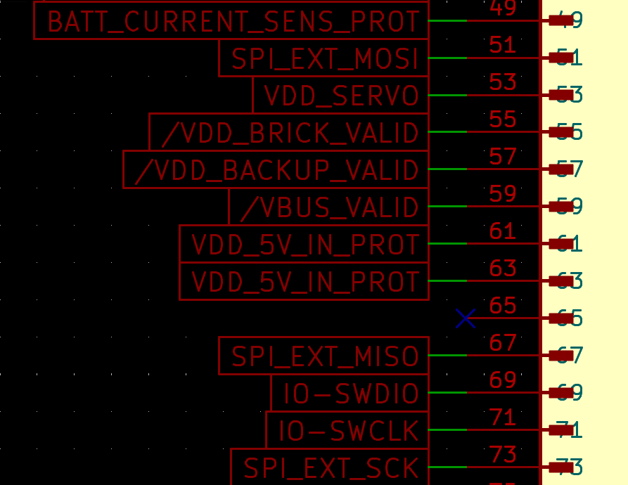
First, you made an error on the FMU power pins. You mentionned 63 & 65 but the correct ones are 61 & 63.
Then, do not connect 55, 57 & 59 to the GND, let them NC. Just connect 61 & 63 to 5V3 and GND from any accessible pad. The Cube should power on. If not, there is something wrong somewhere and you will have to investigate more to find it.
As you suggested, I tired leaving 55, 57 & 59 floating and still the Cube did not power on. No LED indication from the Cube at all.
I tired measuring the voltage on 55, 57 & 59 on the DF17 connector and it was ~0.5V.
I noticed one other thing, when the cube in mounted on the original CB and MicroUSB cable is plugged into the Cube, the Cube turns on and starts blinking. But on my custom CB, when the same is done, again, the Cube has no LED indication. Hope this is useful.
Happy to update that the issue was with the external power section and has been fixed.
Please help me understand the following questions:
If 5V (instead of 5V3) is what is supplied to the POWER1, then VDD_5V_IN_PROT will have no voltage as the PSM (LTC4417) will consider this to be UV?
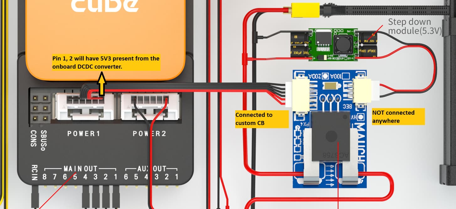
Since I am not going to use a BEC, the Mauch Current Sensor will not have the 5V3 input coming in which is used for offset correction. But since in my custom CB, the Pin 1, 2 of POWER1 has the same net as the output of the onboard DCDC converter, I can just make the connection to the Mauch sensor but leave the input of the Mauch sensor not connected and the offsetting part will still continue to work? (images attached below)
I made the test and i confirm that the pins i suggested should turn it on.
As it does not work and regarding the issue you also have with the USB cable, you can have a short somewhere or a discontinued track in your layout, you have to find it.