Run all Components
Correct Some Codes Before First Run
If you cloned the simple build, no need to edit the file
Edit the file ~/catkin_ws/src/aruco_gridboard/data/layout-my.yaml
Change the line
<param name="camera_info_url" value="package://raspicam_node/camera_info/camerav2_640x480.yaml"/>
to
<param name="camera_info_url" value="package://raspicam_node/camera_info/camerav2_1280x960.yaml"/>
This is because the camera was calibrated with resolution of 1280x960.
Start all ROS Nodes
Connect the aircraft to ground station (eg: Mission Planner) on your remote computer.
Switch back to the Raspberry Pi. Use SSH to login to the Raspberry Pi in every terminal if you are not testing on ground.
Launch raspberry pi camera node module:
roslaunch aruco_gridboard detection_rpicam.launch
Launch mavros module:
sudo chmod 666 <tty port>
roslaunch mavros apm.launch
OR
sudo chmod 666 <tty port>
roslaunch mavros apm.launch fcu_url:=<tty port>:<baud rate>
if you did not set default communication port.
Wait for the EK2 ready, until Request for home position shows up. Open a new terminal, run:
rosservice call /mavros/set_stream_rate 0 10 1
rosrun aruco_gridboard set_origin.py
to set data rate and origin point of your drone. After the python script start, the aircraft should be located in somewhere in Italy.
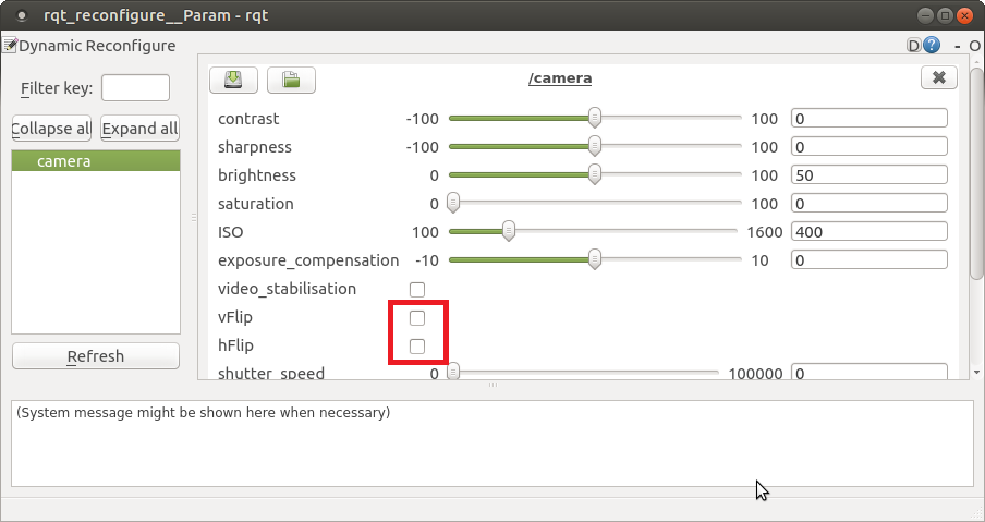
For the first time or if you want to configure the camera, open a new terminal and run:
rosrun rqt_reconfigure rqt_reconfigure
A window will show up and camera parameters can be modified here. For example, select these 2 checkboxes as show below if you mounted the camera upside down.
Open a new terminal, run:
rosrun rviz rviz -d catkin_ws/src/aruco_gridboard/data/aruco_grid.rviz
The rviz should be opened and two 3-axis pose should be at the middle of the screen. They represent the /local_position/pose and vision_position/pose topics, which are the position relative to the aruco board.
Go to the left top corner and find the image tag. Change the topic to /image/raw. The real time image from camera will be shown in the bottom-left corner.
You will see that pose of vision_position/pose change according to the angle of aruco board observed by camera. Pose of vision_position/pose corresponds to the EKF measurement on the Cube. Because of the EKF, vision_position/pose will not change immediately but slowly move to vision_position/pose.
There will be a small delay between the actual movement and pose. The delay can be reduced by increasing the stream rate but please consider the processing power of Raspberry Pi.
The vision_position/pose may not be a flat standing even if the camera is flat. The problem may be located in image processing part. It is still functional anyway.
Load Robot Model to RVIZ
If you want to learn more about URDF model, please visit ROS.org
Install URDF_tutorial Package
Open a terminal and run:
sudo apt install ros-kinetic-urdf-tutorial
Test if Successfully Installed
Go to the package location
roscd urdf_tutorial
Run the default URDF
roslaunch urdf_tutorial display.launch model:=urdf/01-myfirst.urdf
You should be able to see a red cylinder at the middle of RVIZ.
Add Necessary Files
If you cloned the simple build, skip to next session.
Go to my github and clone the following files/folders to the corresponding folders in ~/catkin_ws/src/aruco_gridboard/
data/aruco_grid_model.rviz
launch/detection_rpicam_model.launch
meshes
script/pose_to_tf.py
urdf
Prepare Robot Model
The robot models can be built in the urdf file or load a mesh file into urdf file. If you are using a Raspberry Pi, it probobly would not have enough processing power to load a mesh file.
You can read the urdf_tutorial on ROS.org or look into ~/catkin_ws/src/aruco_gridboard/urdf/test.urdf to learn how urdf works.
You may also download a mesh file, such as .STL, from other websites and load into your urdf file.
To do this, put your mesh file in ~/catkin_ws/src/aruco_gridboard/meshes
Then, change the content of ~/catkin_ws/src/aruco_gridboard/urdf/aircraft.urdf to:
<?xml version="1.0"?>
<robot name="aircraft">
  <link name="robot_link">
	<visual>
      <geometry>
		<mesh filename="file://$(arg meshDirectory)part1.STL"/>
      </geometry>
    </visual>
  </link>
</robot>
which “part1.STL” is the file name of your mesh file
~/catkin_ws/src/aruco_gridboard/urdf/aircraft.urdf and ~/catkin_ws/src/aruco_gridboard/meshes/20_min_drone.STL are drawn by me. You may use them as default.
Solidworks
If you used Solidworks to draw the STL file, put it in the meshes folder and run:
sed -i 's/^solid/robot/' *
before using it.
Run Everything
Connect the aircraft to ground station (eg: Mission Planner) on your remote computer.
Switch back to the Raspberry Pi. Use SSH to login to the Raspberry Pi in every terminal if you are not testing on ground
Open a new terminal, run:
roslaunch aruco_gridboard detection_rpicam_model.launch
Open a new terminal, run:
sudo chmod 666 <tty port>
~/catkin_ws$ roslaunch mavros apm.launch
OR
sudo chmod 666 <tty port>
~/catkin_ws$ roslaunch mavros apm.launch fcu_url:=<tty port>:<baud rate>
if you did not set default communication port.
Wait for the EK2 ready, until Request for home position shows up. Open a new terminal, run:
rosservice call /mavros/set_stream_rate 0 10 1
~/catkin_ws$ rosrun aruco_gridboard set_origin.py
After the python script start, the aircraft should be located in somewhere in Italy.
Convert the /mavros/local_position/pose to tf datatype
rosrun aruco_gridboard pose_to_tf.py
Open a new terminal, run:
rosrun rviz rviz -d catkin_ws/src/aruco_gridboard/data/aruco_grid_model.rviz
A robot model will be bound to the 3-axis pose of /mavros/local_position/pose