I bought a HX4-06006 Power Selection Module, hoping it can help manage my backup power. Is there any instruction/info or application example how it is used and set?
There is nothing to “set”
The demo carrier board drawing shows how it should be setup.
Github The-Cube/tree/master/CB_REV_C_Altium
If you are making a carrier board, please ensure you register it for a free license to use the patent.
I do not have the capabilities/resources to make a carrier board. Is that the only way to make it work properly? Does it have to be connected inside the Pixhawk carrier?
At least I got a schematic now from the PSM folder (the link in your store is broken, pls fix).
Is there a clear PIN-out diagram available to make it work on a breadboard?
I’m ok if it doesn’t do what I expected, if I can’t get it to run, or if I fry it. But the way it is presented I would expect to at least have a chance to do something with it without getting into PCBA manufacturing.
Edit:
Or is it just the power selection circuit of the Cube as a spare part/for R+D and does not have its own purpose?
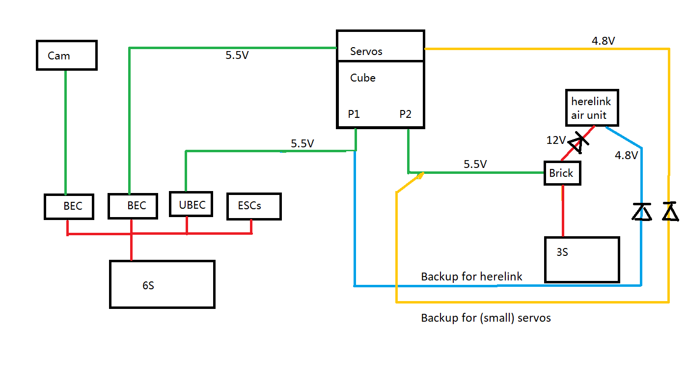
I was hoping the board could manage backup power outside the cube. I have two seperate batteries and UBECs for the Cube. and A BEC from the main power to the servos. What I want is to switch the power of the servo rail to the backup source, if the primary fails, so I can still “sail” down (plane). Also I want a backup fir the herelink air unit.
Basically what I want is this. Not sure if it could work with three diodes, I ave the feeling it would be too simple:
Failure case 3S power: Herelink gets emergency 4.8V from the UBEC.
Servo rail normally draws power from the higher voltage input. Diode protects Brick.
Failure case 6S power: Servo rail gets power from Brick. In that case I am not worried about the reverse voltage on the BEC.
This is not the purpose of the PSM.
The PSM is specifically for use in a carrier board design.
In your case, nothing external should be connected to either P1 or P2
HereLink can be powered with a diode from two 12v sources, but I would also add a fuse in each line to prevent a short circuit on one rail taking out both.
Batt 1(12v)—Diode—fuse—|
.......................|
Batt 2(12v)—Diode—fuse—|—HereLink
...................Zener 14v
.......................|
Ground———————————————————HereLinkThanks for the great info Philip, backup for the herelink was my main concern. I’ll use a MBR15100CT for that. Servo rail probably the same.
I kind of thought the PSM would do something like that digitally when I read “allowing to fail gracefully”. But anyways, more than happy to have a good solution and a better understanding of this kind of circuits, thanks to your advice. I will just keep the PSM as a spare for my Cube.
No worries!