Hi, I want to use my Mini Carrier Board with a Spektrum Receiver,not really sure what to do in the step highlighted in yellow, how I am suppose to break heir connections, should I solder all 3 pads together?
I do not believe it is what I am supposed to do, see picture from the following page, thank you.
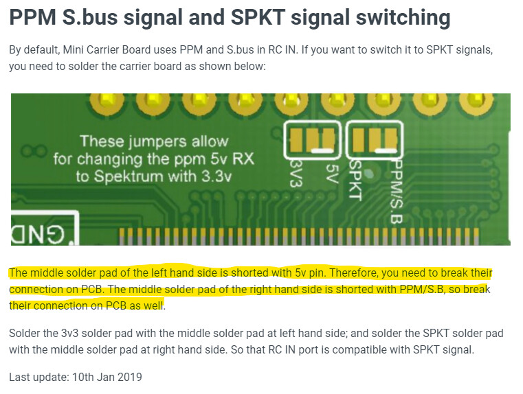
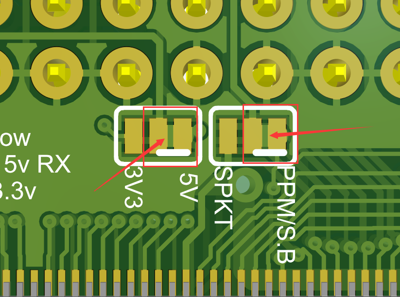
The white lines tell you they are connected with PCB traces. You have to cut them to disconnect the middle and right pad, then solder to short the left and middle pad.
They are jumpers to tell the board which voltage should it use. Don’t solder all 3 together.
Edit: they are connected with pcb trace, not solder.
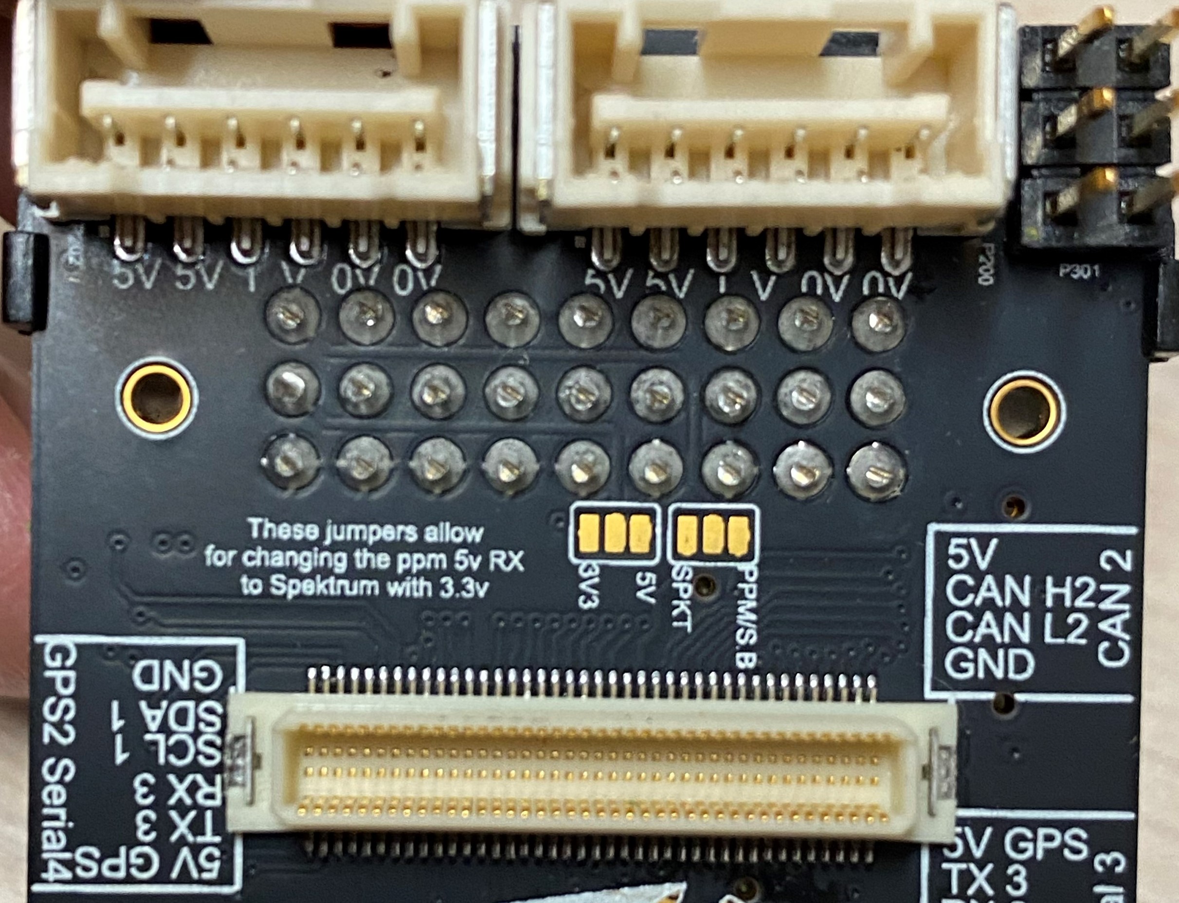
Thank you for your reply, this is what I find confusing, I do not see any solder bridging the gap, my board is new, never been used, I attached a picture of my mini board, it looks just like in the picture above, I do not see any solder I could remove. Any help is greatly appreciated
.
Sorry I was incorrect in the last reply.
They are connected by PCB traces. You can confirm this with a multimeter.
So you have to cut the trace between middle and right pad with a cutter or something similar. Confirm they are clearly cut and disconnected. Then solder the left and middle to connect them together.
Thank you very much, I have check the pads with a multimeter and yes the middle and right pads are connected together. So before soldering the left and middle pad together I have to break that connections.
Now i am starting to think I might have bitten more than I can chew. I assume the traces that need to be removed are where the white lines are on the pictures. I can’t make what needs to be removed when looking at my board.
I was able to remove them and break the continuity, thank you for your time and your help, it was much appreciated as I was lost at what to do.
@Alvin
Mini carrier board sbus/PPM not working but same RC system is working normally on standard carrier board RC in .
Mini carrier board soldering pad also checked with digital multimeter it internally shorted on 5v and other side its shorted with Sbus/PPM.
Then why not its not working on RC IN pin.
I have two Mini carrier board both has same problem.
RC system used is SIYI FT24 on sbus mode out.
When i connect ft24 RC receiver on mini carrier board RC in pin its get powered but seems unbinded with Transmitter but when i add external 5V power supply from other BEC it gets binded.so it must be a not enough power from carrier board to receiver i have tried with connecting only Sbus signal and gnd to the carrier board.