PID setting on large frame

Hi guys

I ask for a little advice or a clue to work on. I am tuning a UAV with Cube Orange, TMotor U8Lite engines and ESC Tmotor FLAME 60A HV 600Hz (6s-12s). The frame is 120cm and 28 "propellers with 12S power system

everything ok and flies well … but I’m not completely satisfied !! the bench setting was done with some parameters of the “initial parameters” excel sheet and a lot was done in the field with autotune on all axes.
However it is still too “soft” even though the “roll / pitch sensitivity” parameter in QGC is all the way to the left (full twitchy !!!) and even though the AUTOTUNE_AGGR parameter via mission planner (0.05 to 0.10) is 0.1 !!! (the frame is rigid and not elastic or flexible !!!)(the frame is rigid and not elastic or flexible !!!)
As if the PIDs on the Roll and Pitch axes were not very reactive; in fact, after a Roll or Pitch shift, the aircraft assumes the hovering position again with some more corrections than other previously built machines.

Certainly the engines are bigger and less reactive because they are “slower” given the inertia and the masses involved but I ask if there is any other parameter that I can modify to make the system more reactive.
In the calm of the wind everything is fine but when I have to face stronger winds, I fear that these hesitations in the search for stabilization can create a pendulum effect that is accentuated more and more until the crash.

thanks to all the friends who will be able to give me suggestions

I have had this issue in the past with larger drones and I just ran an autotune at above 0.1 aggressiveness. MP gives me a warning that it is out of range - but it didn’t cause any major issue. Just a more aggressive tune to lead to better PIDs.

Thanks Manav for the important information. If I may ask you, what value did you put? that is, how far have you gone? Thank you

Can you upload a .bin log file to dropbox or similar, then post a link to it here

hi Shawn,

thanks for the reply … I put the link of the .log file which unfortunately is large but at the moment I only have this available

thanks again for the help

(or .bin : Dropbox - 2021-03-11 14-51-53.bin - Simplify your life )

Any special reason to use 4.1 Dev instead of a Stable version? Usually bigger frames and props are too expensive to risk, but so long as you are aware not all Dev features and changes have had suitable flight time.

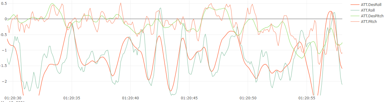
Attitude control needs work

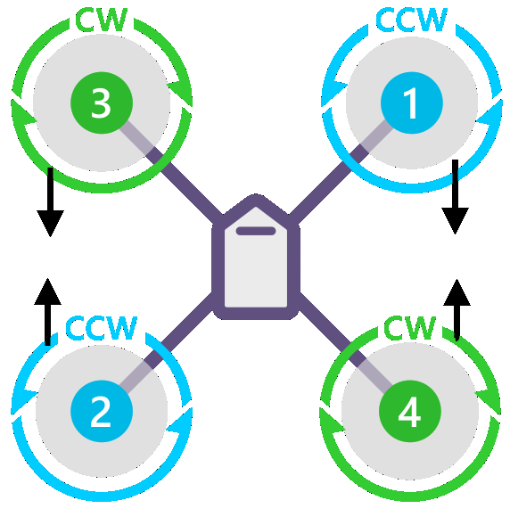
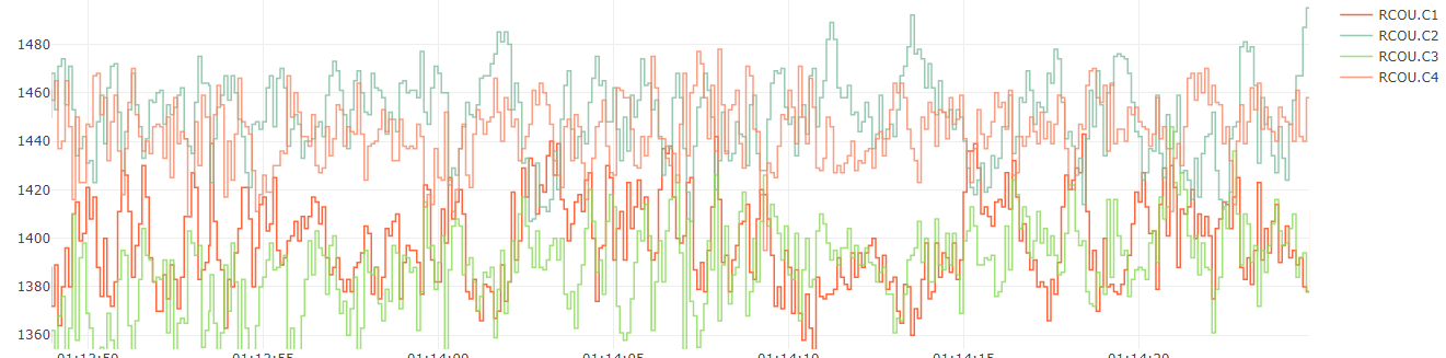
Motors 2 and 4 are typically working harder than 1 and 3, indicating a slight weight imbalance to the front.

Current monitoring is not working, best to set that up as soon as possible. It’s another worthwhile diagnostic tool. Maybe just your BATT_AMP_PERVLT,0.0489 is wrong. A Cube power brick is normally BATT_AMP_PERVLT,39.877 but you have something non-standard for the Voltage scale, so I’m guessing the current scaling will be non-standard too.

Vibrations are good, Z axis is a little higher than ideal but just something to watch out for in case it becomes an issue.

I would set these to help be as safe as you can
BATT_FS_LOW_ACT,2
FENCE_ENABLE,1
FENCE_TYPE,3
This fence setting will make you wait for a good GPS 3D fix and home position, but it’s not much to ask for one of these big craft to do a RTL properly when it needs to.

For the T-Motor Flame ESCs I’d usually advise to set these:
MOT_THST_EXPO,0.2
MOT_PWM_MIN,1100
MOT_PWM_MAX,1940
There’s some conflicting evidence out there, but so far I think the balance favours these settings.
Even rerun the ESC calibration too, just in case the ESCs do respond to that. Some doco says they can’t be calibrated and those PWM settings must be used, and some says they can ALSO be calibrated.

You’ve got ATC_INPUT_TC moving all over the place during flight. That’s OK but probably just set it at 0.2 to 0.25 for these big frames. 0.15 is the default and is quite twitchy to suit smaller more acrobatic frames.
ATC_INPUT_TC is not your core problem, it’s the attitude control.

For fixing the attitude control, I’m going to suggest a few things in sequence.
First set these, not much change here
ATC_ACCEL_P_MAX,25300
ATC_ACCEL_R_MAX,25300
ATC_ACCEL_Y_MAX,10800
ATC_RAT_PIT_FLTD,10
ATC_RAT_PIT_FLTT,10
ATC_RAT_RLL_FLTD,10
ATC_RAT_RLL_FLTT,10
ATC_RAT_YAW_FLTT,10
PSC_ACCZ_I,0.34
PSC_ACCZ_P,0.17

and lets rationalise the PIDs a bit, since they were quite different per axis and not working well anyway
ATC_ANG_PIT_P,6.0
ATC_ANG_RLL_P,6.0
ATC_RAT_PIT_D,0.00625
ATC_RAT_PIT_I,0.10
ATC_RAT_PIT_P,0.10
ATC_RAT_RLL_D,0.00625
ATC_RAT_RLL_I,0.10
ATC_RAT_RLL_P,0.10

then set up the logging for a test flight before enabling the Harmonic Notch filter:
INS_LOG_BAT_MASK,1
INS_LOG_BAT_OPT,0

Do a test flight in Althold for a minute or two, maybe a bit of gentle movement to test your RC control now, but nothing radical. Mostly we just want hover for now.
Let’s see the .bin log file from that flight.

Then we will enable the Harmonic Notch Filter and probably run Autotune if everything is working out OK.

If you get to do the above tests and want to progress, this is what you need for the next stage of Harmonic Notch filtering:
HNOTCH phase 2
INS_HNTCH_ENABLE,1 <- set this then refresh params to see the rest
INS_HNTCH_MODE,1
INS_HNTCH_REF,{hover_thrust}
INS_HNTCH_FREQ,{peak freq from FFT}
INS_HNTCH_BW,{peak_freq / 2}
INS_HNTCH_ATT,40
INS_LOG_BAT_OPT,2 - capture post-filter gyro data, test fly again to generate a new log and recheck
HNOTCH phase 3
INS_LOG_BAT_MASK,0
INS_LOG_BAT_OPT,0 - no extra logging, assumes HNOTCH is working great

but you’ll have to read up on it first and work out how to read the FFT in MissionPlanner. Best to just do the test flight and post a link to the new .bin log file :slight_smile:

1 Like

Hi Shawn

First of all, I have no words to express my gratitude for these really valuable advice. Finding so much availability is really a rare commodity!
A lot of meat on the fire and I will try to do the tests in these days (weather conditions permitting because they are days of mistral wind at 25/30 m / s and the UAV is not called Luna Rossa :smiley: !!)
As for the voltage / current monitoring, I can confirm that I have a Mauch that works at 50V (12S) but on the Cube Orange I have problems reading the current on pin 15 (or 14 … I don’t remember well at the moment). This is another thing I will have to check
I’ll do the tests very soon and I’ll let you know by posting the logs.

again a big thank you

The Mauch BATT_AMP_PERVLT value should be about 32.6 (roughly) and it should have been provided to you with the sensor. The pin may be correct, just that scaling value is wrong.

hi Shawn

I am still finishing analyzing some things and I only managed to do one flight a couple of days ago but with wind at over 40kmh. However I flew for some time in AltHold with the parameters you indicated. (in the attached file please look at only the last flight of the 3 present … it is the most significant)

I apologize if I did not specify the previous payload (i.e. zero !!) but this time I loaded a payload of about 2Kg and from now on it will always fly like this)

Obviously the weather did not allow me to appreciate the stability but we are taking small steps.

thank you again

Could be the wind but pitch and roll definitely need some more tuning.
Why is the last fight most significant? You lowered the ATC RAT P and I values for some reason and I think attitude control got worse.

Try putting a believable value in BATT_AMP_PERVLT

Probably not much point in the wind, but it would be most useful to set INS_LOG_BAT_MASK,1 and wait for a still day.

Edit: I meant did you see anything different about that last flight? What were your thoughts?

I may be able to shed some light on this. If you have to run low P values it would indicate to me something I usually refer to as Secondary Mass Oscillation. this occurs when something like a battery for example is mounted on rubber and it sets up an oscillating frequency that is read by the IMU but is alien to the response from the propellors. It is sometimes misread as prop vibration when in fact it is the motors pulsing to try and iron out the unwanted movement. It has also been attributed to over dampening of large gimbal assemblies. It can also occur when Carrier boards are mounted on soft sponge rubber and the cables start to oscillate.

Hi Denny,

thanks for your contribution and I understand perfectly what your point of view is. It is very interesting what you say and often all this is underestimated, especially the concept of free cables in the pipes that can generate instability. Really worth considering.
However in my UAV everything is well fixed … starting from the batteries and wiring. The Cube Orange is not fixed on rubber pads but on rubbery double-sided tape (not the one supplied); despite this I do not have great phenomena of vibration (as evidenced by the very kind Shawn who examined the log)

I am waiting for the weather to improve because ours is a windswept area but I have a question for everyone … I have a couple of doubts that are in contrast with each other … that is, that the Cubes are not perfectly capable to manage large frames, but at the same time I can think of UAVs for agriculture that have extensions beyond 2 meters and not all of them have DJI. (maybe they use CUAV ?? … but Cuav is not basically a Cube ??)
So I can accept the fact that I am not yet very expert on Pix (I have always worked on DJI starting from Naza and then arriving at WooKong, A2, N3, A3, etc. and all their SDKs) but I cannot believe that a control unit like this evolved may have problems on large frames

Can you confirm this thought? (I hope not, otherwise I have to throw everything in the toilet !! :-D)

Hello,

because my topic is similar, I would attach my topic here. We have dodeca setup with 12xMN801-120KV and 32" Props and Flame 60A HV ESC´s. Total weight of the drone was 54kg

We made the first flight with settings from a smaller dodeca setup. The drone flew without crashing :wink: but still needs improvements.

Flight Test

Log and Profile

Before thinking to use autotune on this bigger drone, it would be great if someone could take a look. I already saw the suggestions from Shawn, which we would like to include here.

Thanks in advance!

The actual pitch and roll has oscillations

and there seems to be a constant offset to pitch and roll. I would do the Calibrate Level -> set up the aircraft with the prop disc level (motor to motor, front to back, left to right , all level). Don’t try to level just the flight controller itself -> then press the Calibrate Level button in MissionPlanner/Mandatory Hardware/Accel Calibration.

Your PIDs seem a bit high plus D terms are maybe a bit low. Lets standardise them a bit:
ATC_ANG_RLL_P,6.0
ATC_ANG_PIT_P,6.0
ATC_RAT_RLL_P,0.12
ATC_RAT_RLL_I,0.12
ATC_RAT_RLL_D,0.0075
ATC_RAT_PIT_P,0.12
ATC_RAT_PIT_I,0.12
ATC_RAT_PIT_D,0.0075

Then use the spreadsheet in the link to set all the values it suggests given your prop size and batteries. We are looking for a bunch of updated ACCEL , FLT and MOT_BAT values here, and the correct battery voltage settings, so don’t ignore anything that you think “we dont need that yet”.
You already have MOT_THST_HOVER / MOT_PWM_MAX / MOT_PWM_MIN / MOT_THST_EXPO correct so don’t change them.
And set BATT_FS_CRT_ACT,1

After all that (everything, dont try changing just some params), try a hover test looking for oscillations and lets see that log file.

The alternative to using this spreadsheet is do the Beta updates to MissionPlanner and press Alt A while the aircraft is connected.

EDIT: You may want to set ATC_INPUT_TC,0.2 for a softer RC input being a larger aircraft.

I just noticed you didnt have this set
INS_HNTCH_REF,0.331
…and the other values could use some adjustment I think
INS_HNTCH_FREQ,72
INS_HNTCH_BW,36
There’s also a big peak in the frequency range at 36Hz which seems a bit low for nomal prop vibrations, maybe a resonance somewhere. It would be good to see the FFT again after some dynamic flight, and you might be able to put a static notch on that.

hi Shawn

I’m analyzing everything you advised me in early April. For the weather and the limited time to devote, they don’t allow me to have an immediate reaction :slight_smile:

In the meantime I am trying some things and following your coins, I see that the system starts to work better.
At the same time I am also building a quad and many parameters suggested by you find space in this frame.

I need a little info: to increase stability, in addition to the natural dihedral of 5 degrees, can I orient the motors by 2 or 3 degrees? and in which direction? do you recommend it?
I enclose a diagram where the orientation of the motors is indicated by the arrows (joining motors 1/4 and 2/3 while diverging 1/3 and 2/4