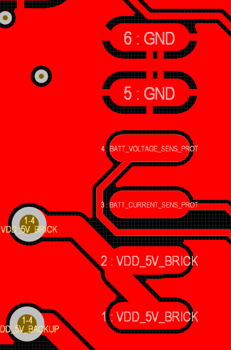
Our team is attempting to make our own BEC to feed into the Cube Orange and other peripherals. The BEC that came with the cube orange has a current sense output that feeds into pin 3 of the Cube Orange Molex power input (shown below).
What is the best way to go about implementing the sense outputs (both current & voltage) to be compatible with the Cube Orange firmware; what is the protocol that is being used?
After some experimenting with current draw using servos, we found that the voltage on the current sense did not increase linearly with increasing current draw, and seemed to be using some other pwm related protocol.
The voltage and current sense inputs are analog up to 3.3v maximum.
The power brick supplied with the Cube has a basic shunt resistor for current sense. This type of sensor is famously non-linear and inaccurate with low currents. Up around 10amps or more they are fine.
Ideally you would use a Hall Effect sensor for current.
Thank you for the response. We are planning to use a hall effect sensor yes.
However, I am wondering more about what type of signal we should be feeding to the pixcube, in order for the firmware to correctly decode our current sense voltage signal and display something sensible to QGC?
Our current experiments show the following for a 150mA current draw and 300mA current draw (photos below).
There is no “protocol”.
It’s just an analog voltage up to 3.3 volts maximum.
In firmware you set BATT_AMP_PERVLT to scale the tiny analog voltage to represent real amps.
And similarly with BATT_VOLT_MULT for the voltage.
I dont know what a “pixcube” is since there has never been such a thing, but I assume you have a Cube Orange since you’ve found this forum. Originally there was a Pixhawk and that name got diluted by copies of various quality and Proficnc firmly adopted the Cube name to differentiate from the low quality manufacturers and copiers - there are other good manufacturers out there too. There’s probably a much longer story…