Hello Everyone., I am working on a new project.
I believe Pixhawk Cube Orange+ is Compatible with TMotors 8 in 1 ESC " TMOTOR FPV C-55A-8S-8IN1 Professional Cinematic ESC".,
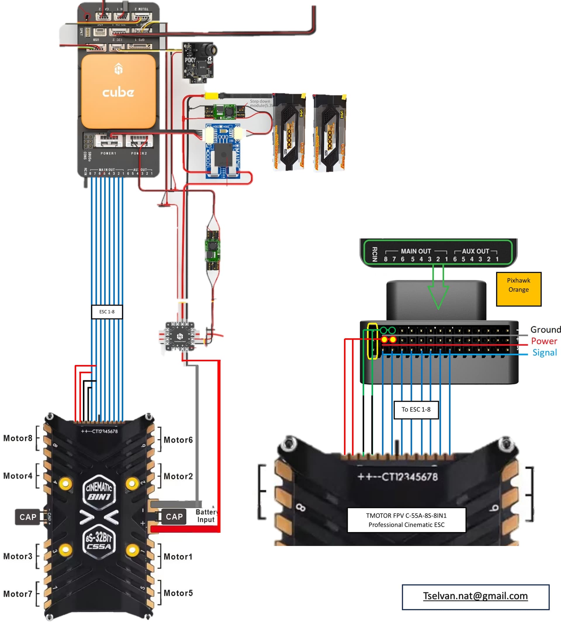
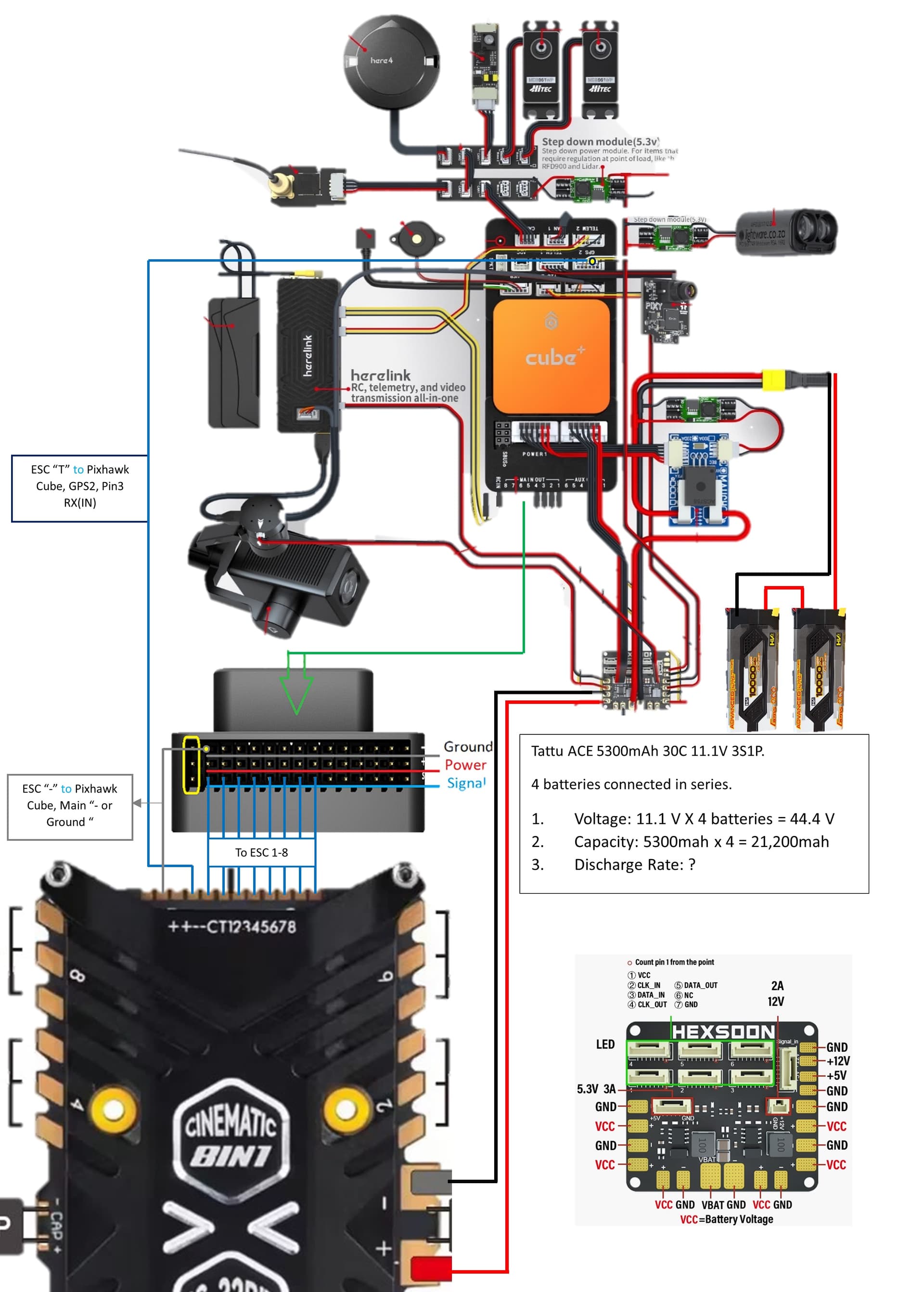
I am trying to connect both., but I have a lot of confusion about the wiring, I have attached the wiring sketch, Please correct me wherever I am wrong. Thanks in advance.
It would be nice if T-Motor provided details
But anyway… Leave those “Power” wires terminated and not connected to anything - they will be full battery voltage.
Leave the “C” current wire terminated and not connected to anything too. I remove them from the connector housing on the 4in1 ESCs I’ve used, so no one is ever tempted to connect them to anything.
You only need the 8 signal//motor wires, Ground, and Telemetry.
The Telemetry wire should go to UART4 Rx pin, and set these parameters
EDIT sorry, GPS2 (SERIAL3) or Telem2 (SERIAL2), whichever is unused, and change those params to SERIAL3 or SERIAL2
SERIAL3_BAUD,115
SERIAL3_OPTIONS,16
SERIAL3_PROTOCOL,16
The Signal wires have to go to Main Out 1 → 8
And you have to load Arducopter latest firmware ver 4.5 (Latest) to get the DSHOT via IOMCU functionality. Download it from herre, then “load custom firmware” in MissionPlanner
I already linked to the correct file you need
https://firmware.ardupilot.org/Copter/latest/CubeOrangePlus/arducopter.apj
Set these parameters:
BRD_IO_DSHOT,1
MOT_PWM_TYPE,3
SERVO_BLH_AUTO,1
SERVO_DSHOT_ESC,1
If any motors are spinning the wrong way you can reverse them with this bitmask parameter
SERVO_BLH_RVMASK
and use this to set the number of poles you motors have, just to scale the RPM data correctly
SERVO_BLH_POLES
If you dont use the Latest 4.5 firmware, you have to run the 8 ESCs with PWM on the main outs, or only maximum 6 on Aux outputs with DSHOT. Both of those options are sub-optimal.
I believe the 4.5 firmware will be safe enough to use, it’s had quite a bit of testing so far.
After all that you should see in Messages something like:
RCOut: DS600:1-8 PWM:9-14
and on the Status tab there should be actual ESC data, like voltages and temeratures.
1 Like
Thank you so much Shawn, I have a few more doubts., Please help me.
I have pointed out all connections in sequence, as printed on the board, and the “T” is Telemetry. I can understand that ESC 1-8 is to be connected to the Flight Controller’s signals. Power, Ground, and Current to be left without connecting to anything. Where, and to what should I connect the telemetry port? Also, there are only 12 connection points on the board, and in the printed information on the board, it says there are 14 connection points like “+±-CT12345678” where one power and Ground are extra. Is this how they mention the power and ground?
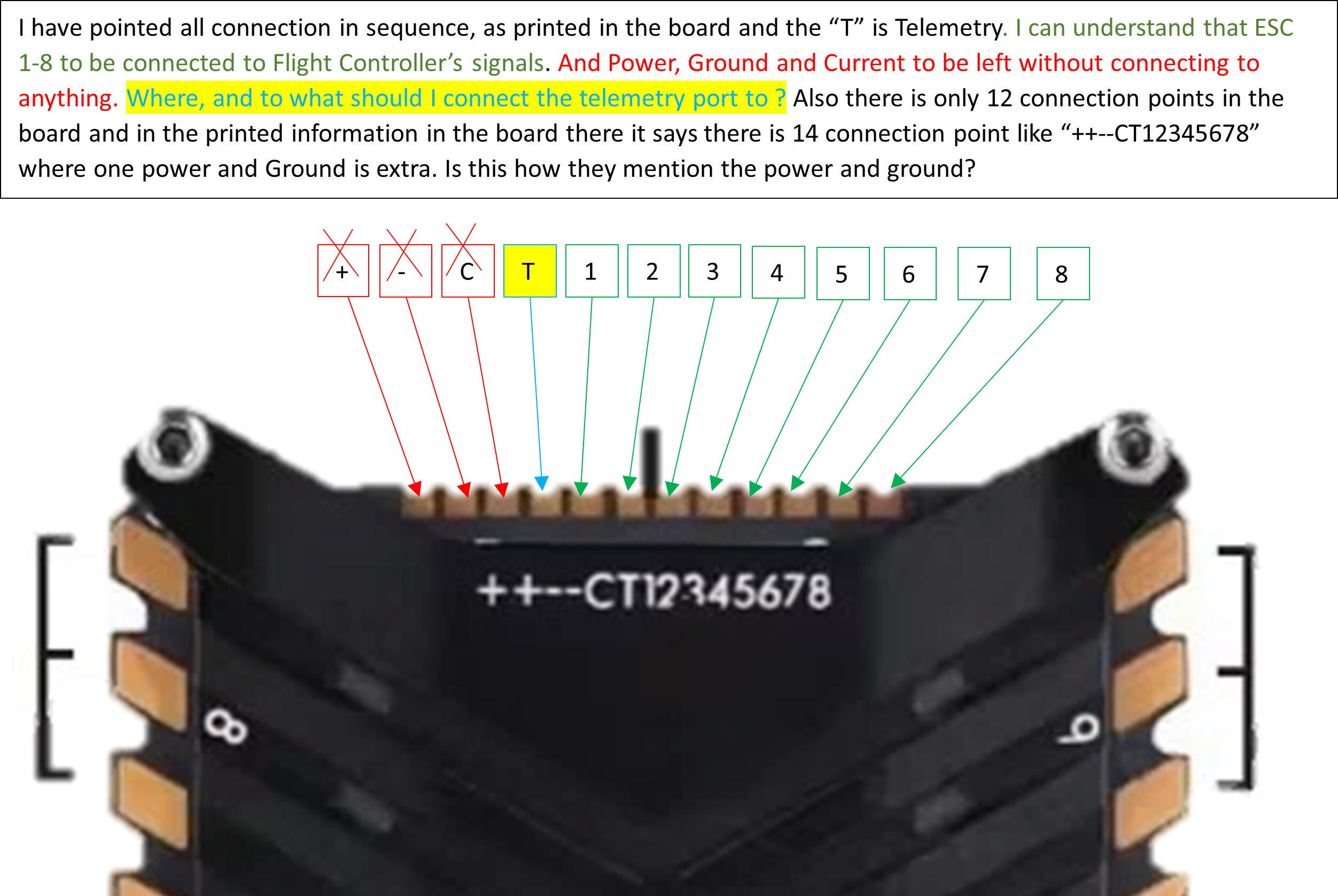
The “-” (or Ground) can connect to the - of the Cube Main Out pins.
It’s just the “+” and “C” that you want to avoid.
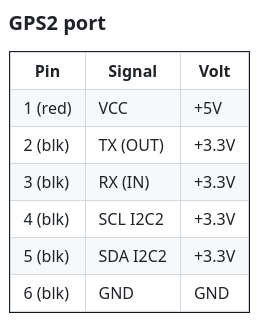
The “T” telemetry wire goes to the RX pin of the GPS2 port if you dont have a second serial GPS. You will need to find a cable you might have already or make one to join to that T wire.
Also just to be completely clear, the “Latest” firmware version 4.5 is not the mainstream Stable version. It is probably about to be released as Beta soon, so is very close to being mainstream - there might be a few changes or bug fixes before it is released.
1 Like
Thank you Shawn, I’ll test the circuit and let you know.
Sure, but he could also eliminate the Mauch current sense board entirely, and rely on the ESC’s current reading – albeit available in telemetry too. Then use a Mauch 021: PL 4-14S HYB-BEC / 1x 5.3V off the ESC vbat pins. He can enitrely eliminate that PDB by going with the 2-output version; or 3 if he needs 12v. Four items (2 BECs, a Current board, and a PDB) to just one Mauch BEC.
1 Like
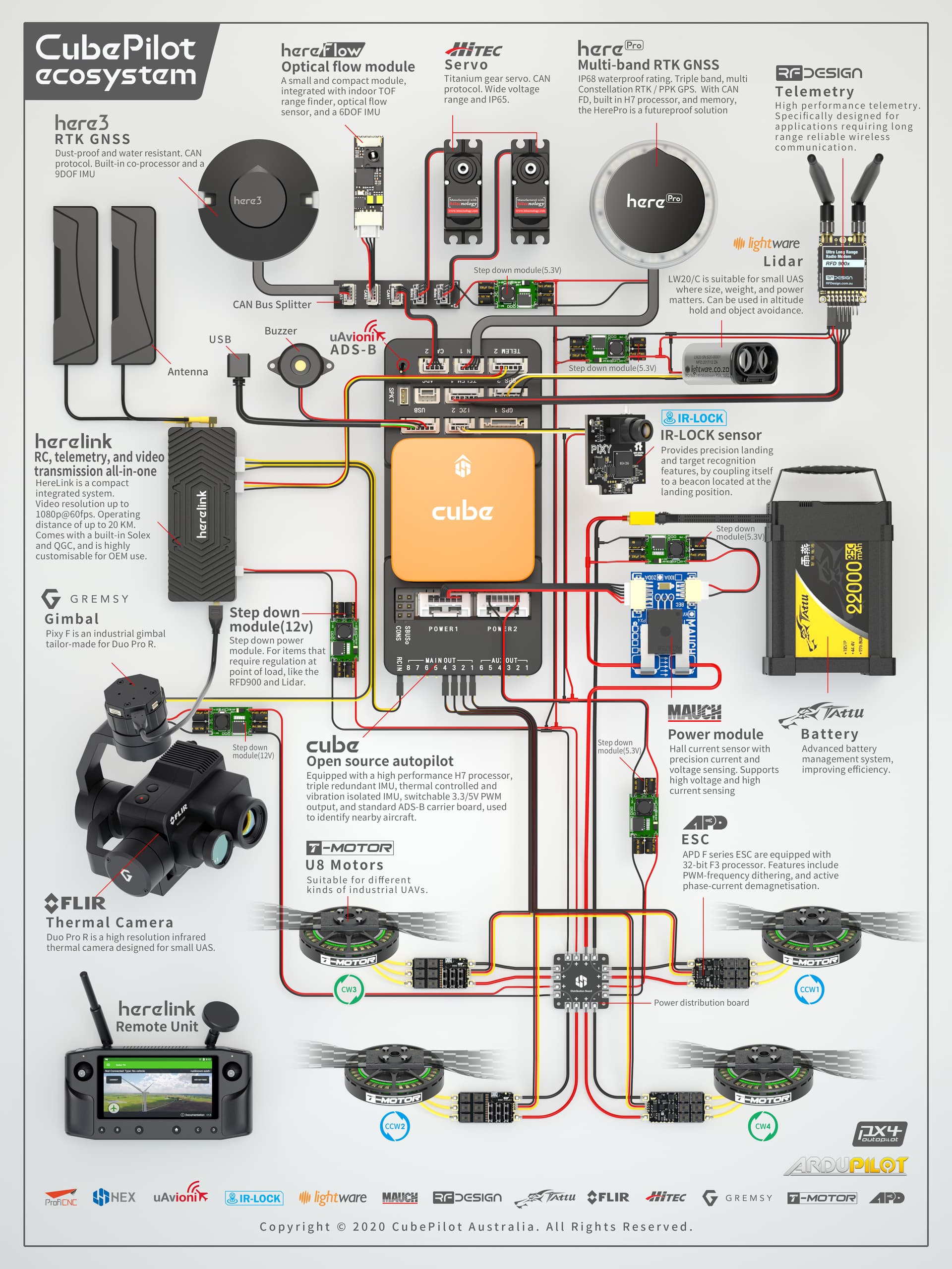
Thank you So much, David, that is a good idea, and Yes, I just wanted 3 Outputs, 2 x5.3V, and 1 x 12V, I checked the Mauch website, and they have the 024: PL 4-14S HYB-BEC / 2x 5.3V / 1x 12.0V, I’ll use this when upgrading my project. Presently, I purchased Mauch 078: HS-200-HV/2*15CM 8AWG and PDB board. I’ll update you here when I deploy your idea. Also, I am using the Ardupilot Pixhawk Orange connection. The components are different, but the connections are the same (Image posted). This is my first project of this kind, so if you have any suggestions like you said or any documents for me to consider, please share them, it would be a great help. Thanks again.
Au
You’re good for now. There is a lot to be learned about ArduCopter, and adding any more hardware will just make it harder getting to a maiden flight.
1 Like
Hi @davidbitton and @xfacta, I have doubts in connecting hardware, particularly in the discharge rate of the battery, and worried that it will fry the boards. I’m using the following configuration.
- Battery: Tattu ACE 5300mAh 30C 11.1V 3S1P battery connecting 4 batteries in series
- ESC: TMotors, CINE55A 8S 8IN1 32BIT ESC, has rated current 855A and peak current 865 A, Input Voltage 3-8s.
- Power Module: Mauch power module 200A, 8AWG, HV 4-14S.
- Power Distribution Board: Hexsoon Power Distribution Board
The connection is made as shown in the drawing. Since I am connecting the battery in series, the circuit specifications will be as follows:
- Voltage: 11.1 V X 4 batteries = 44.4 V
- Capacity: 5300mah x 4 = 21,200mah
- Discharge Rate: 30C * 5300mAh = 159A (1C = 5.3A). (is this the correct way to calculate?)
- Discharge Rate: 30C * 21,200mAh = 636A (1C = 5.3A). (Or this is correct?)
or the discharge rate will be only 30C even if we connect the batteries in series?
If the second one is correct, then the Power module cannot handle it, right? As the rated current is 200A. Please help me with this., how does this work? and how much should i be worried about the discharge rate?
Also, I am trying to achieve longer flight times, that’s why I have connected the batteries in series, it reduces the overall weight. and I’m building a calculation sheet and that’s why I’m getting these kinds of doubts.
Doubt 2: Please check the connection between ESC and Flight Controller, I have connected based on the ideas given in the discussion.
Thanks in advance.
You have an 8S ESC and you plan on feeding it 12S (4x 3S). Puting 12S on the ESC is likely to release the blue smoke.
1 Like
You dont ever mention what motors you have, and it is the motors (with props) that will DRAW the current (amps). It means almost nothing to say 159 Amps are available, unless motors were big enough to use all that available current.
I suggest 6S to keep that ESC within limits.
When batteries are in series, the available current is limited by the “smallest” battery.
When batteries are in parallel, the available current is added up.
All these extra connectors and wires add weight and points of failure. More batteries dont always equal more flight time, it could be less!
Go to ecalc and put in your weight and other details, see what flight times you get. For the price of a pair of cheap plastic props you can get a subscription and save yourself a lot of guesswork:
1 Like
@xfacta Thank you for the Flight Time calculator link., I will try it.
Full battery voltage needs to be applied to the ESC, and the ESC needs to be able to draw whatever current it needs from the battery pack. So the wire size is fairly critical, and keep these main power wires as short as possible.
The advantage of using a 4in1 or 8in1 ESC is that becomes your power distribution board. You will still require a BEC to power the flight controller.
As @davidbitton says I would just use the Mauch BEC to run the flight controller. The Cube needs a regulated +5 volts DC supply. A BEC has relatively low current capability, and is our term for a voltage regulator or regulated power supply. It can not pass much current, typically 3 amps or something like that.
The idea is to have as few connectors as possible in between the battery and the motors. You need a battery connector of course, but the main battery supply wires should be soldered to the ESC and the motor wires to the ESC (they build them just with solder pads for that reason).
The power wires to the BEC can be soldered to the ESC/battery wires too. Also add on a set of power wires, say #20 gauge, for powering other things, like Herelink, camera and so on.
It takes some skilful soldering, and a good soldering iron, to get all that done without making a mess, so practice first.
1 Like
I’m working through your battery worksheet and putting a few numbers into ecalc.
Generally you are much better off with 1 single battery pack with less connectors and wiring, than trying to connect multiple packs in parallel or serial if you dont have to.
With a small copter, you will be lucky to fit on just one pack, BIG copters use multiple packs because there is often no choice.
1 Like
technically 5.3v
1 Like
Thank you, @xfacta for the recommendation and Ideas. I’ll go with one battery. Also, let’s see if we can achieve anything good, theoretically with the sheets. let me know, once you correct it.
Hello and thank you for this information.
I have the same esc and have followed the wiring and parameter suggestions outline in this thread by @xfacta
BRD_IO_DSHOT,1
MOT_PWM_TYPE,3
SERVO_BLH_AUTO,1
SERVO_DSHOT_ESC,1
I am not seeing the RCOut: DS600:1-8 PWM:9-14 on messages.
Mine shows RCOut: PWM:1-14
I have tried 4.6dev as well.
I think this is a typo? MOT_PWM_TYPE,3.
That sets it as brushed motors.
I have selected MOT_PWM_TYPE,6.
I have the battery connected while connecting to MP to view the messages.
I have tried GPS2 and Telem2 with the same results.
Also not seeing any telem data on the Status tab for ESC’s.
Any further suggestions would be very much appreciated.
1 Like
Selvan Hello,
As you’re doing a project that has similar current requirement to my project’s and are using a power Distribution board similar to the one I want to use, I would like to ask if you could help me with the confusion I am having. I want to use the Hexsoon Power Distribution Board to power an 8 in 1 or two 4 in 1 ESCs, which will power my 8x 32 Amps on 100% throttle for each motor. A problem that I see is that the Hexsoon Power Distribution Board says it can provide 6 x 25A continuously, so I am not motivated to use this PDB. Yet, I see that in the connection diagram that you provided you have powered the 8 in 1 ESCs from 2 pins that are supposed to provide 25A. Can you elaborate on how have you made this work? Like I can’t get it. Thanks in advance.
Has anyone else had success with this setup? It would be great to have it working.
Thanks in advance
@xfacta
I’ve got a QuadX8 with 2 4in1 ESCs run by a CUAV V5 Nano via DSHOT - just changing it to a Cube Orange now but not finished yet. There’s no reason why it wont work.
Mine is not flying yet but is configured ready to go
8/04/2024 4:19:10 PM : RCOut: DS300:1-8 PWM:9-13
8/04/2024 4:19:10 PM : IOMCU: 420 1001 411FC231
8/04/2024 4:19:10 PM : CubeOrange 00330033 3131510E 31363832
8/04/2024 4:19:10 PM : ChibiOS: 6a85082c
8/04/2024 4:19:10 PM : ArduCopter V4.5.0 (53ad2c2a)
BRD_IO_DSHOT,1
MOT_PWM_TYPE,5
SERVO_BLH_AUTO,1
SERVO_DSHOT_ESC,1
MOT_PWM_TYPE,3 is your problem - change to 5
Also update the firmware to 4.5.0 - it is now designated as stable.
EDIT:
I see much further back it was me that gave you the wrong parameter value “MOT_PWM_TYPE,3” so that is my fault - Sorry!