How many current sensors and power 5v becs are onboard the kore board and orange cube?
1
There are additional 5v and 12v sources for accessories, but only 1 supply with voltage and current sense for the Cube.
asking for a redirect. I do not see any labeling for the in general plugs on the kore board. Also have 2 ubecs additional. one for the auxilary plugs and one for power 2 plugs. Where do I plug in the aux ubec other than one of the ubec arms? I am choosing no ubecs on the esc’s.
thanks.
I was wrong actually.
The Kore carrier has two independent +5v supplies for the Cube.
It only has one voltage and current sensor as far as I can tell.
Also when you set up the voltage and current monitoring, these settings are “more correct” than the ones in the documentation, especially the BATT_AMP_OFFSET value:
BATT_AMP_OFFSET,0.37
BATT_VOLT_MULT,15.26195
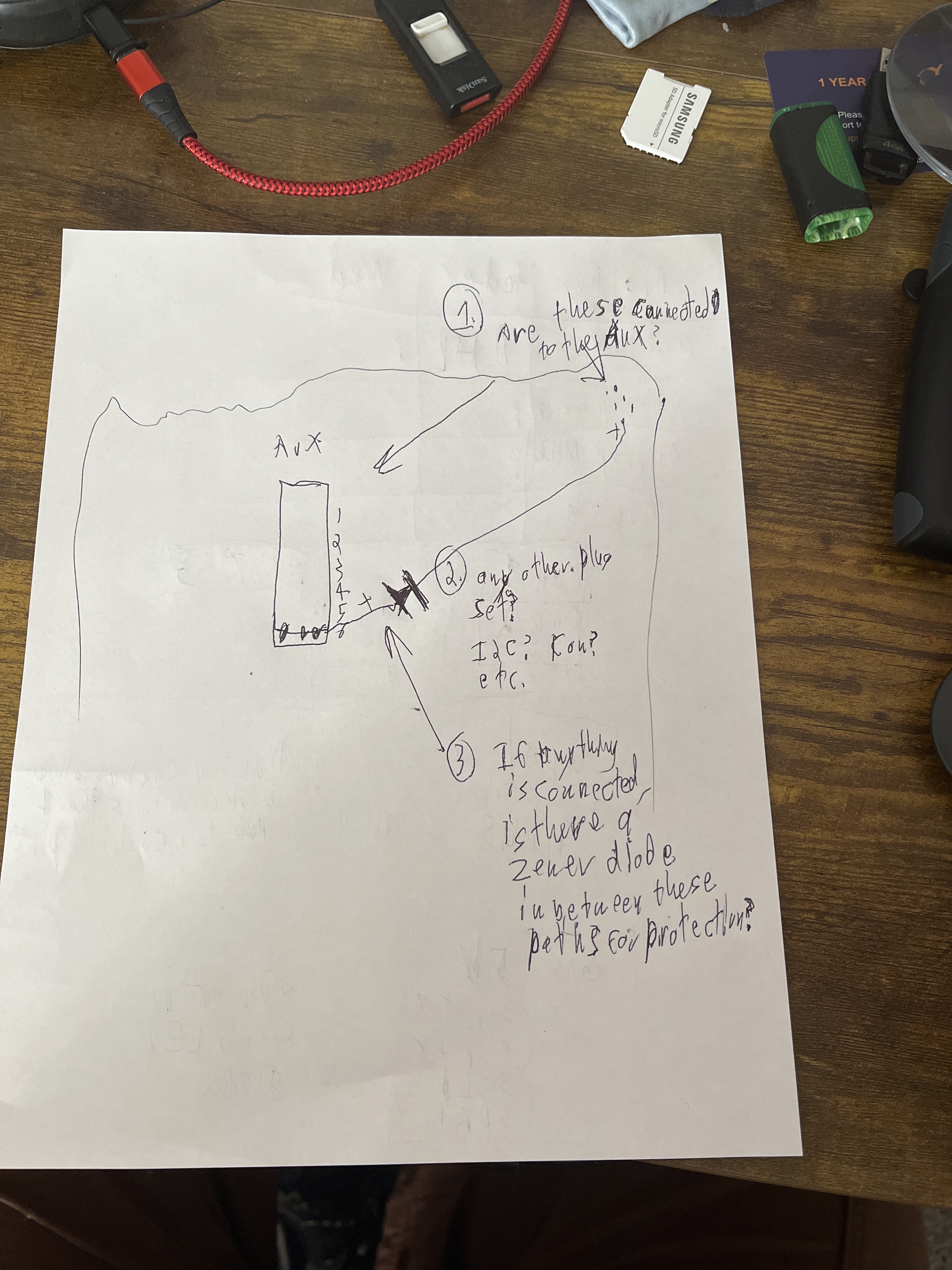
Is it possible to add a current sensor for the other 5 volt, or is it battery 2 individually set? Will the ammeter(s) signals interfere with each other on the positive voltage since it is the same battery? Also, is there a possible 5 volt bec/12 volt choice on that second bec, Or is it static? How are these paths arranged?
thanks.
How is the PWM esc lines and PWM aux plugs hooked up together? I am going to power a seperate bec for them and want to make sure that everything is powered. I wont use all the aux ports, so can I connect a bec there? Want to make sure there are no zener diodes or other trap that would block the flow to all the needed sections.
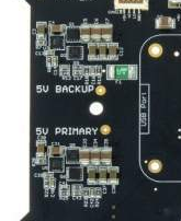
See my pic there - the two BECs are identical and built into the Kore. They are fed by the same (single) battery input, therefore only one voltage and current sensor.
The Cube already monitors the +5v supply after all sources are combined and fed into one common supply internally. This is measured and logged as POWER.Vcc
Also Ardupilot has status flags and logging for the various voltage inputs and status’ , logged as POWER.Flags
1   MAV_POWER_STATUS_BRICK_VALID      // main brick power supply valid
2   MAV_POWER_STATUS_SERVO_VALID      // main servo power supply valid for FMU
4   MAV_POWER_STATUS_USB_CONNECTED    // USB power is connected
8   MAV_POWER_STATUS_PERIPH_OVERCURRENT   // peripheral supply is in over-current state
16  MAV_POWER_STATUS_PERIPH_HIPOWER_OVERCURRENT   // hi-power peripheral supply is in over-current state
32  MAV_POWER_STATUS_CHANGED         // Power status has changed since boot
You can not use your own BEC without breaking out contacts between the Kore and the Cube - you might as well design and build your own carrier then, or just use the standard carrier.
Do you have ESCs that actually need an external supply? That would be odd these days.
Or do you mean you’ll be running servos from some of the Main or Aux outputs?
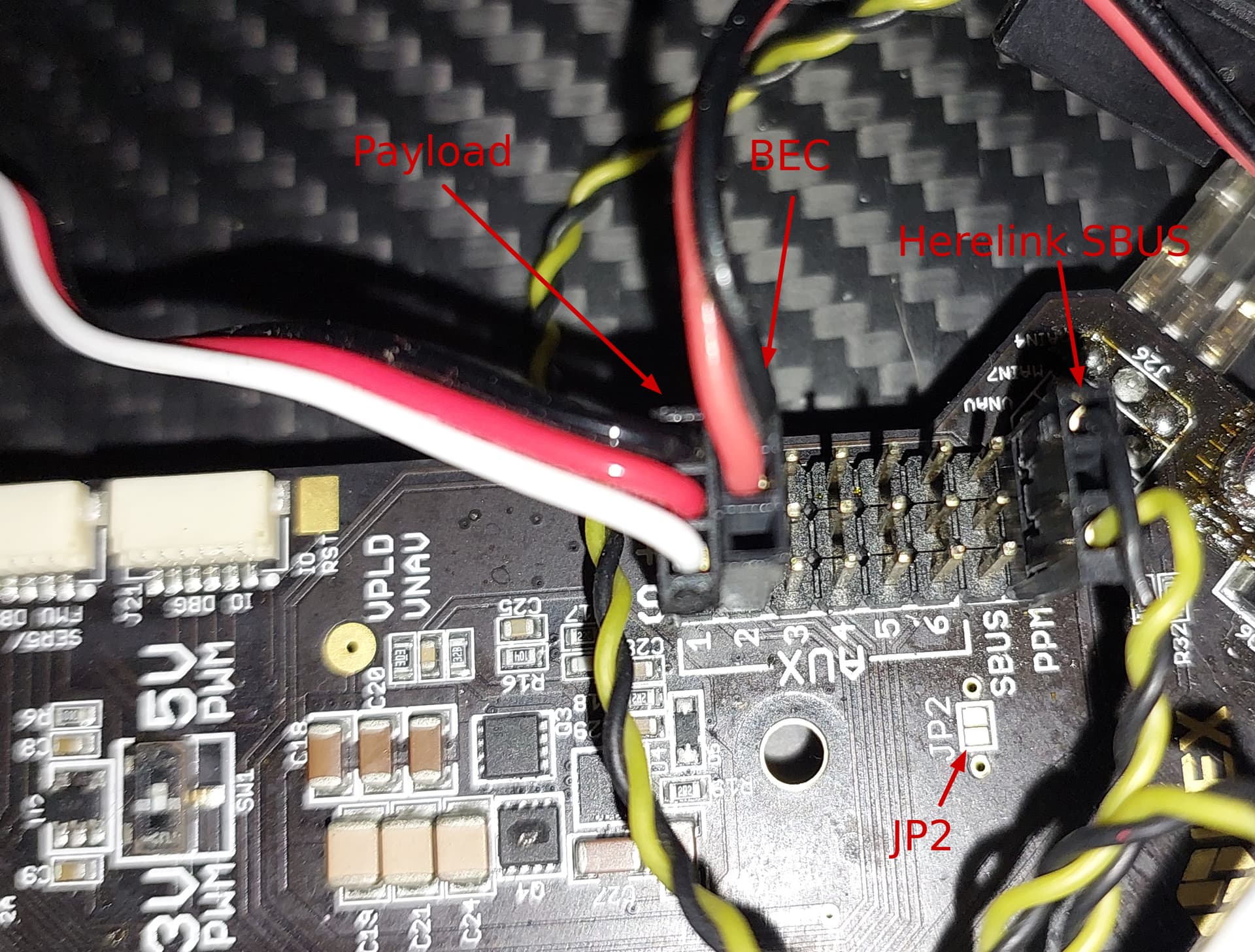
There’s two ways to power the AUX pins.
- put a solder bridge on JP2, this supplies 5v to the Aux + pins, never connect a BEC
- connect a BEC, but never bridge JP2
And regarding the Main PWM pins, from the doco:
By default, the board does not supply power to the ESC PWM connections. However, if no BEC is available to power the ESCs, the user may bridge JP1 with solder to provide 5.3V from the board to the ESCs. If JP1 is bridged with solder, do not plug a BEC into the ESC connections.
Thought there maybe a switcher between the 2 becs onboard. Wanted to make sure the current sensor was not stuck only on one bec. If so, would like a current sensor on both.
Possibly servos for a camera or gimble motors with basecam if siyi camera axis motors are not stable.
The reason that I ask is I may need to supply power to the aux. Do not know if power may be cut off from other sources if I charge one of the ends near the esc’s
The current sensor and voltage sensor is monitoring the battery input, which fans out to the ESC power connectors and everything else including onboard BECs. So there’s no such requirement for the voltage or current sensor to be “connected” to the BECs that supply the Cube - those inputs are internally “switched” and monitored (Vcc and Power.Flags - see above).
When I say internally, I mean within the Cube via “ideal diodes” of sorts - there’s a whole bunch of advanced power circuitry in there.
See what I wrote about the AUX pins and JP2 - it’s all in the Doco.
If you have low power accessories that only require 5v, then bridge JP2.
If you have servos or something that requires a significant supply, connect your BEC to the AUX + and - pins (and leave JP2 disconnected).
A fairly simple 5v BEC connected to AUX pins would be enough to run a couple of small servos.
Depending on the gimbal controller, you might be better off with a serial or SBUS connection. The AUX outputs would certainly be able to send individual PWM signals if that’s required. You might need to explain more about why you think a zener is needed. And I couldnt follow about the connectors near the ESCs.
The Main outputs at the ESC connection points are labelled with a pin for 12v, and there are other connectors with 5v , 12v and battery voltage available.
I dont think you will affect power to other parts of the Kore or Cube. The 5v outputs are fused. The 12v output is NOT fused.