Hello, I am an electrical engineer designing a custom carrier board for the Red Cube. I haven’t been able to find any mechanical drawings that show the dimensions of the locations of the 2 connectors and the mounting holes on the bottom of the cube, could some from CubePilot please provide a mechanical drawing of those? Thanks so much!
Here’s a start Cube Red Standard Carrier Board Pinout | CubePilot @philip is there a drawing anywhere with dimensions?
Hello, I am also wondering if this drawing exists. The link @Gary_Mortimer is not fully sufficient and raises some questions. Through my part creation exercise using the Cube Red 1 3D model, the mounting holes align perfectly when the cube is offset by 0.18mm to the left, which leaves the connectors slightly offset (see A>B below). The mechanical drawing requested by the OP would be incredibly helpful.


Hello, @philip I was wondering if you might have the documents rquested in this post?
@jannett Did you ever find an answer? I’m in the same boat. Trying to build and scale a platform on Cube Red and this is the latest roadblock. 
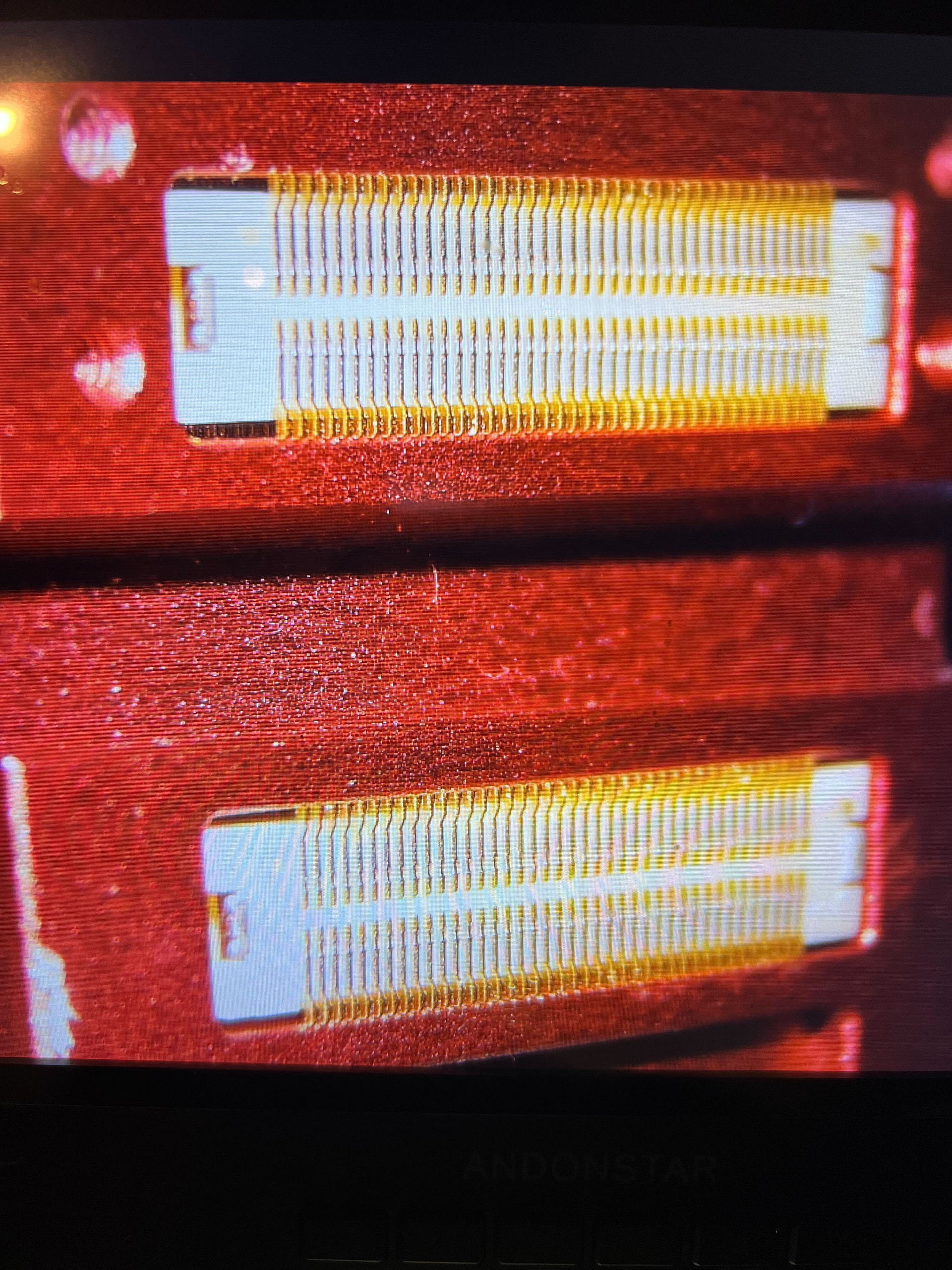
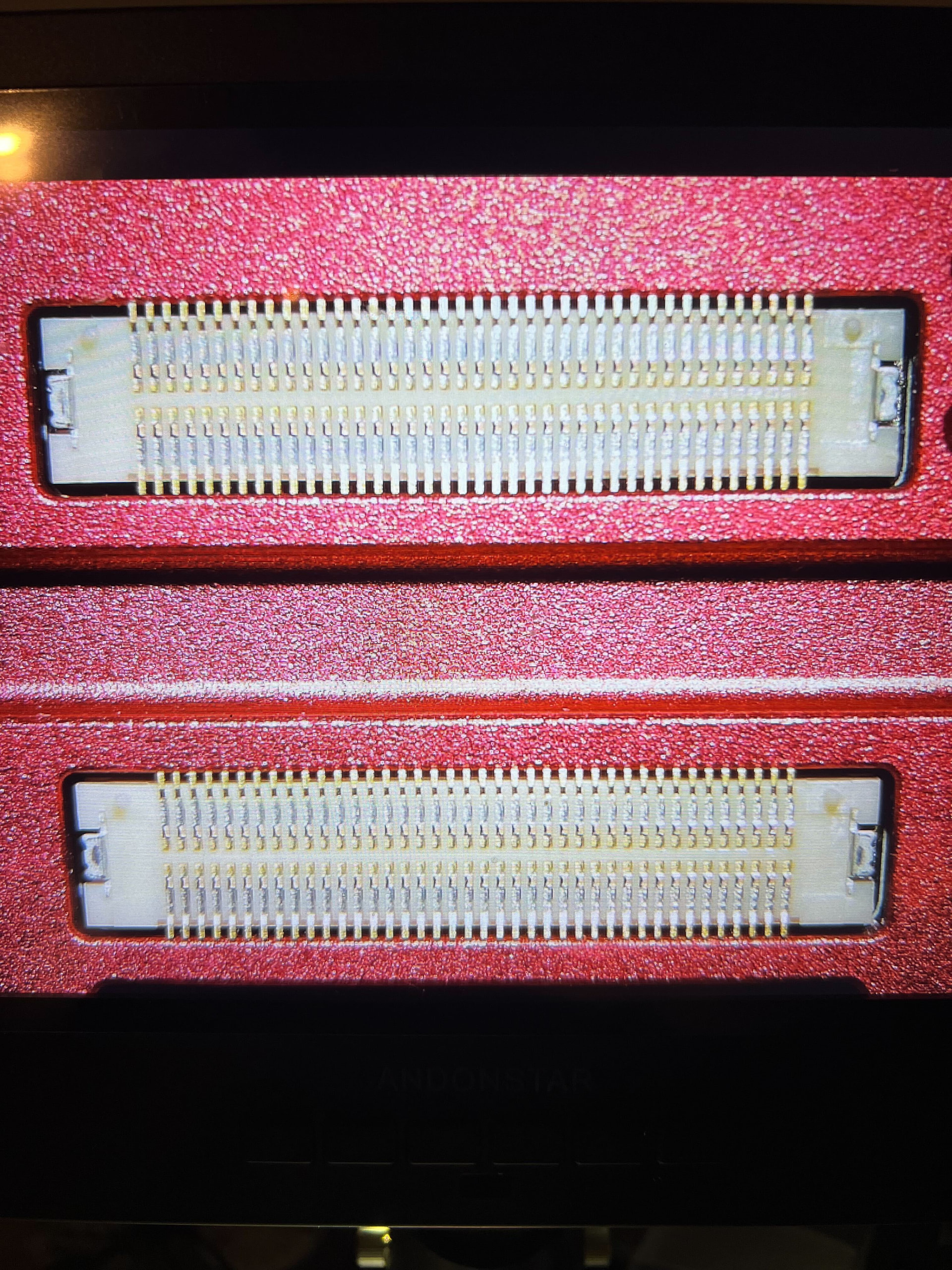
@Gary_Mortimer @philip is there any way you can provide this drawing or even a STEP of the cube red carrier board? we did a spin creating a footprint as best as we could but it is not exactly right and the cube tolerances around the connectors is (too) tight! (the connector pins touch the casing, see pictures) The main issue is that while it is not screwed down, allowing for more play ethernet connection is established, when the cube is reasonably tightened connection is not established. Please provide a STEP or drawing of connectors and mounting holes.