@Federico in the parameters you have SERVO5_FUNCTION set to 56 it needs to be -1.
Hello:
Thanks a lot. I´ve changed:
SERVO5_FUNCTION to -1
CAM1_RELAY_ON to 1
CAM1_TYPE to 2
RALLY_DEFAULT to 0
and it finally worked.
I say again, thanks a lot to everybody and I upload my parametrics in case it will help anyone else.
ag6 pixhawk cube con camara trigger ok.zip (5.7 KB)
CubeOrange Arducopter 4.5.6
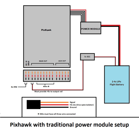
I measure the + (Red) and - (black) pins, 0.0V, and measure S (Signal) and - (black), 0.0V. Main out + pins (1-6) are currently open, and not connected to ESC.
Do I need to supply external power (5V/ 3.3V) to Main Out + pins? Something like that?
Is the servo rail in the article referencing Main Out + pins? What about AUX power referring to?
I am concerned about burning the CubeOrange (not a cheap board).
I am still confused about the entire Power Architecture.
# https://ardupilot.org/copter/docs/common-gpios.html#version-4-2-and-later
BRD_PWM_VOLT_SEL,0 # 3.3V
RC11_OPTION,28 # Relay1 On/Off
RELAY1_DEFAULT,0
RELAY1_FUNCTION,1 # Relay, save and refresh
RELAY1_PIN,107 # MainOut7
SERVO1_FUNCTION,33 # M1
SERVO2_FUNCTION,34 # M2
SERVO3_FUNCTION,35 # M3
SERVO4_FUNCTION,36 # M4
SERVO5_FUNCTION,37 # M5
SERVO6_FUNCTION,38 # M6
SERVO7_FUNCTION,-1 # setting a PWM/SERVO/MOTOR output to be a GPIO function
17/09/2024 13:24:51 : PreArm: RELAY1_PIN=107, set SERVO7_FUNCTION=-1
17/09/2024 13:24:20 : PreArm: RELAY1_PIN=107, set SERVO7_FUNCTION=-1
17/09/2024 13:23:58 : RC11: Relay1 LOW
17/09/2024 13:23:56 : RC11: Relay1 HIGH
17/09/2024 13:23:54 : RC11: Relay1 LOW
17/09/2024 13:23:50 : RC11: Relay1 HIGH
17/09/2024 13:23:49 : PreArm: RELAY1_PIN=107, set SERVO7_FUNCTION=-1
17/09/2024 13:23:46 : RC11: Relay1 LOW
17/09/2024 13:23:40 : RC11: Relay1 HIGH
17/09/2024 13:23:18 : PreArm: RELAY1_PIN=107, set SERVO7_FUNCTION=-1
17/09/2024 13:22:47 : PreArm: RELAY1_PIN=107, set SERVO7_FUNCTION=-1
17/09/2024 13:22:25 : RC11: Relay1 LOW
17/09/2024 13:22:25 : RC10: MotorEStop LOW
17/09/2024 13:22:25 : RCOut: PWM:1-14
17/09/2024 13:15:41 : CubeOrange 00420019 3239510C 38363839
17/09/2024 13:15:41 : ChibiOS: 6a85082c
17/09/2024 13:15:41 : ArduCopter V4.5.6 (7ce11b41)
Yes, you’ll have to supply external power to the pwr/gnd pins. Just make sure you solder the wires properly else it might generates a lot of heat and melt the plastic part.
Thank you, I managed to get it working with RC11. I get 3.3V when BRD_PWM_VOLT_SEL,0, and 5.0V when BRD_PWM_VOLT_SEL,1 on the signal pin Main out 7 with ground measurement.
1 Like
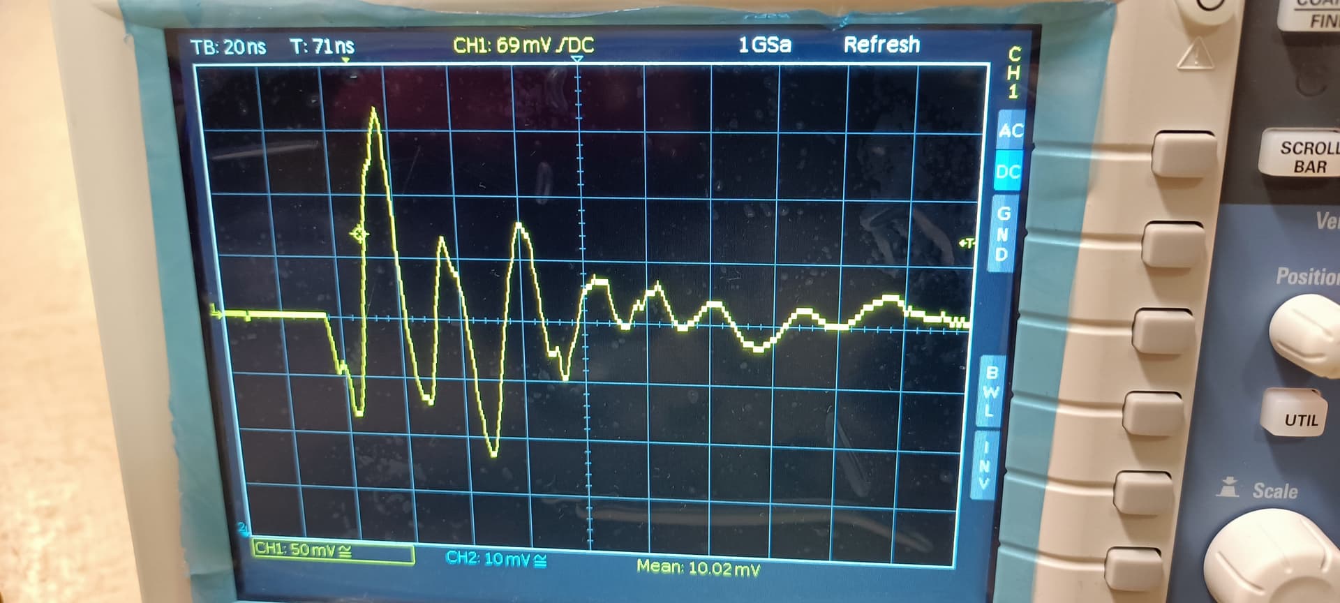
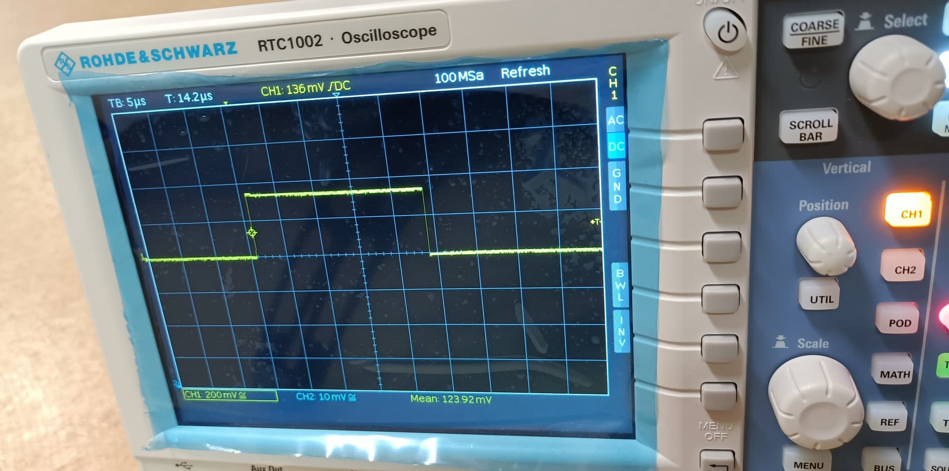
How do I resolve this false Relay trigger (transients, 170 mV) when connecting the battery?
Arducopter 4.6.1, CubeOrange.
BRD_BOOT_DELAY, 0 or 3500 # no improvement
BRD_PWM_VOLT_SEL,0
RELAY1_DEFAULT,0
RELAY1_FUNCTION,1
RELAY1_INVERTED,0
RELAY1_PIN,107
SERVO7_FUNCTION,-1
[edit]
On further investigation with a software reboot using Mission Planner while keeping the Relay powered, Actions→Preflight_Reboot_Shutdown, the pin produced a pulse (380 mV); however, the relay did not produce a false trigger. So, I think there are 2 issues here. One, the Relay module is unable to suppress the false trigger when connecting the battery, two, the CubeOrange is generating some pulses during powering up and reboot.