This one has taken a lot longer than it frankly should have however I have released the STL files for a mod that allows you to convert the Herelink throttle from self centring spring loaded to non centring for fixed wing users.
The How To video is finally done

The Mod

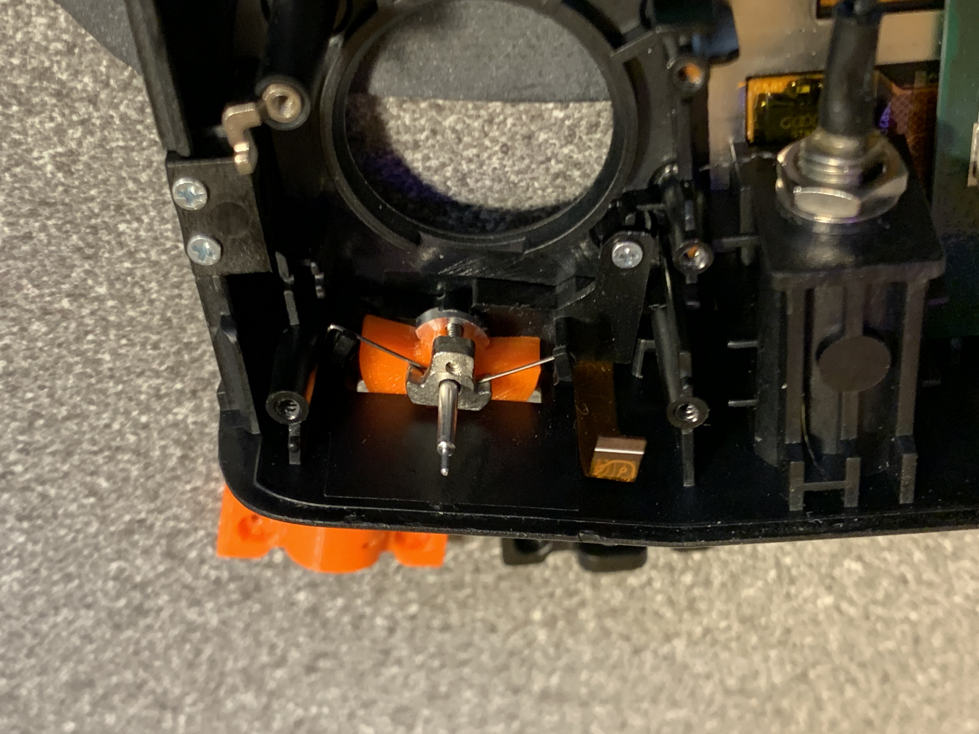
The modification consists removing the spring and arm mechanism for the vertical movement and replacing the gimbal bracket on the LH side of the gimbal mount.
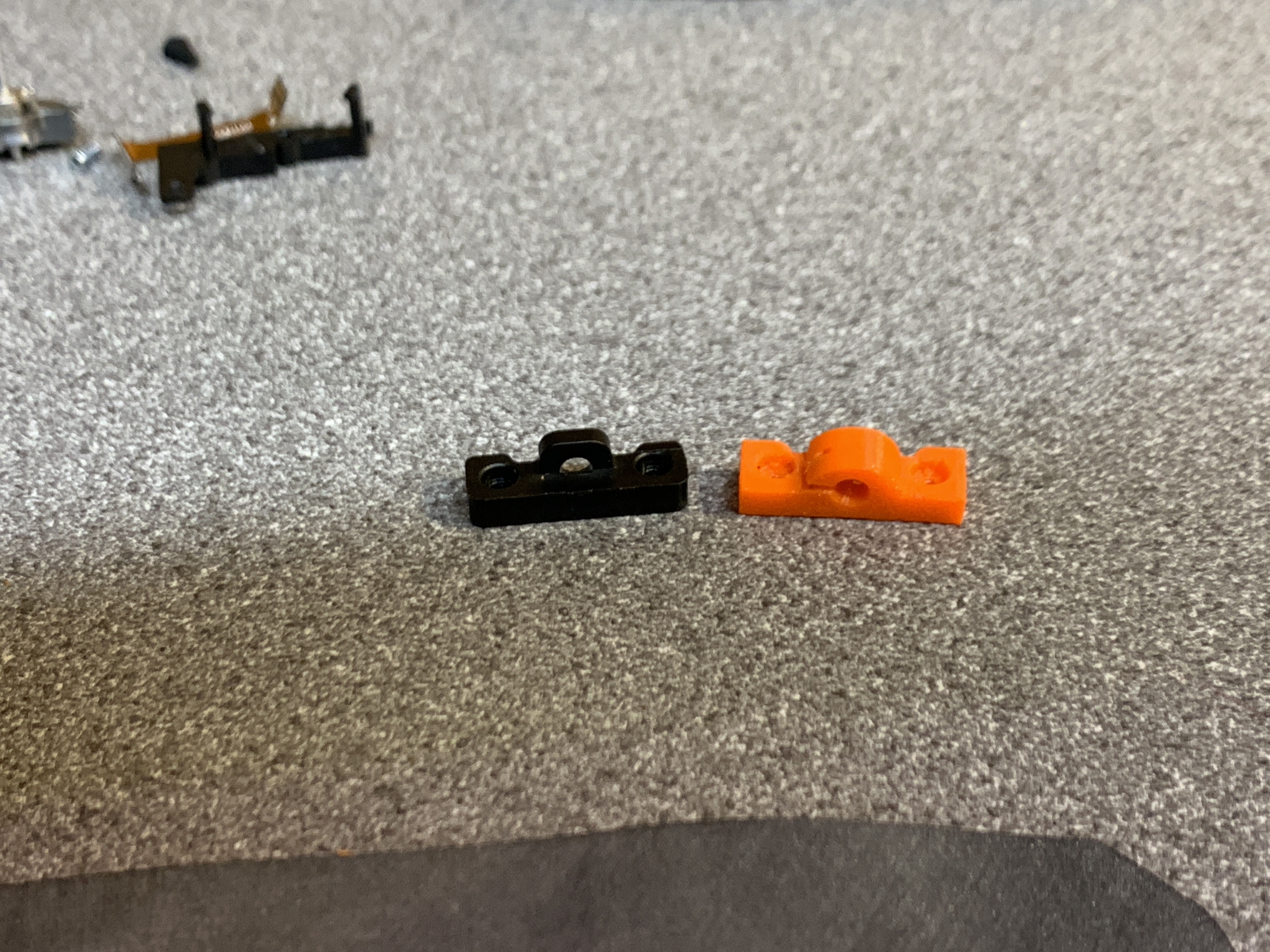
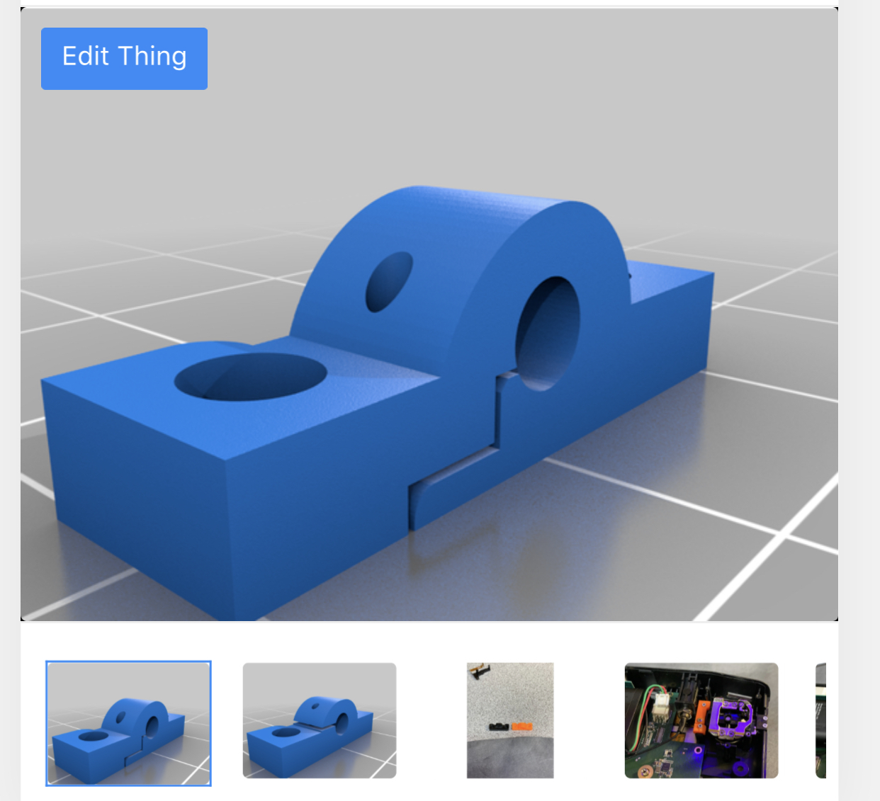
The reason for the new bracket is when you remove the spring system the gimbal is extremely lose and no safe for use. This new bracket has tighter tolerance as well as a built in tensioning option by adding a 3rd small screw to close to clamp tighter.
You can perform the mod with out actually replacing the bracket and instead adding a 0.5mm washer between the existing bracket and gimbal however the new bracket is advised.

This new bracket comes in two versions, both work it’s just slightly different ways of clamping. Imo V4 is the best option as is moves the screw a little further from the gimbal shaft and I was unhappy how close it was but you may need to open it up after printing.
You will need a 3D printer to make these or know someone with one. I advice printing in as much detail as possible on their side, I printed in PetG 0.07mm for best results. If there is anyone in the UK that wants done I’m happy to print a batch up and post them once once this madness is over.
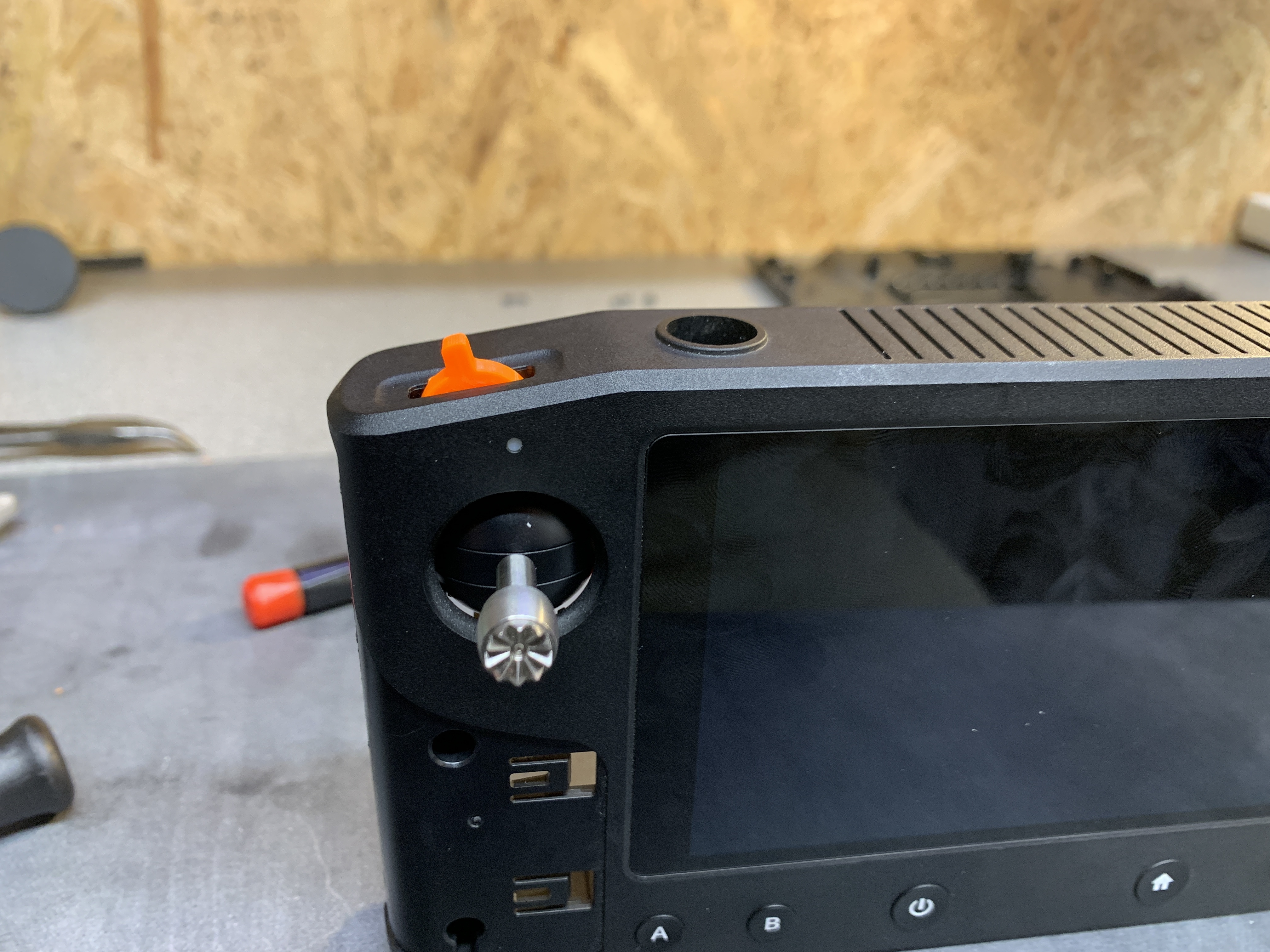
Further to this I have also designed a replacement gimbal wheel, this replaces the current metal onc, it’s more of a lever design that I personally prefer.
With regards to installing these I want to say Herelink is a delicate piece of equipment and performing any mods come with risk, unless your 100% confident you should not consider doing these. Also note they could have an affect on your warranty too should something go wrong.
I will be putting out a video on how to do this on the weekend however the basics are
To convert the throttle on Herelink.
1: Remove the side grips, these are held on with clips and adhesive tape. Carefully from the side prise them upwards and outwards until the adhesive releases.
2: once removed this will reveille screws at the front. Remove 2 x screws from each side.
3: remove the 2 screws from the rear.
4: from the side gently separate the two half’s of the case, then slowly work your away around until the back comes free.
Note: there are no cables going from the front to rear however you should be very careful around the top end as the GPS antenna and some thin ribbon cables are located along there.
4: once open disconnect battery
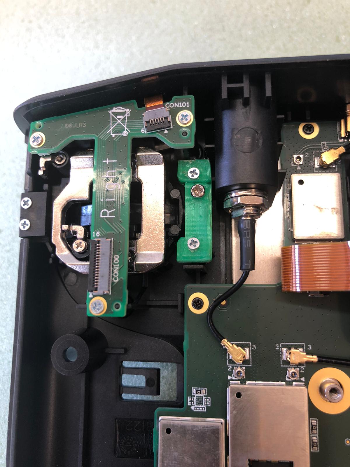
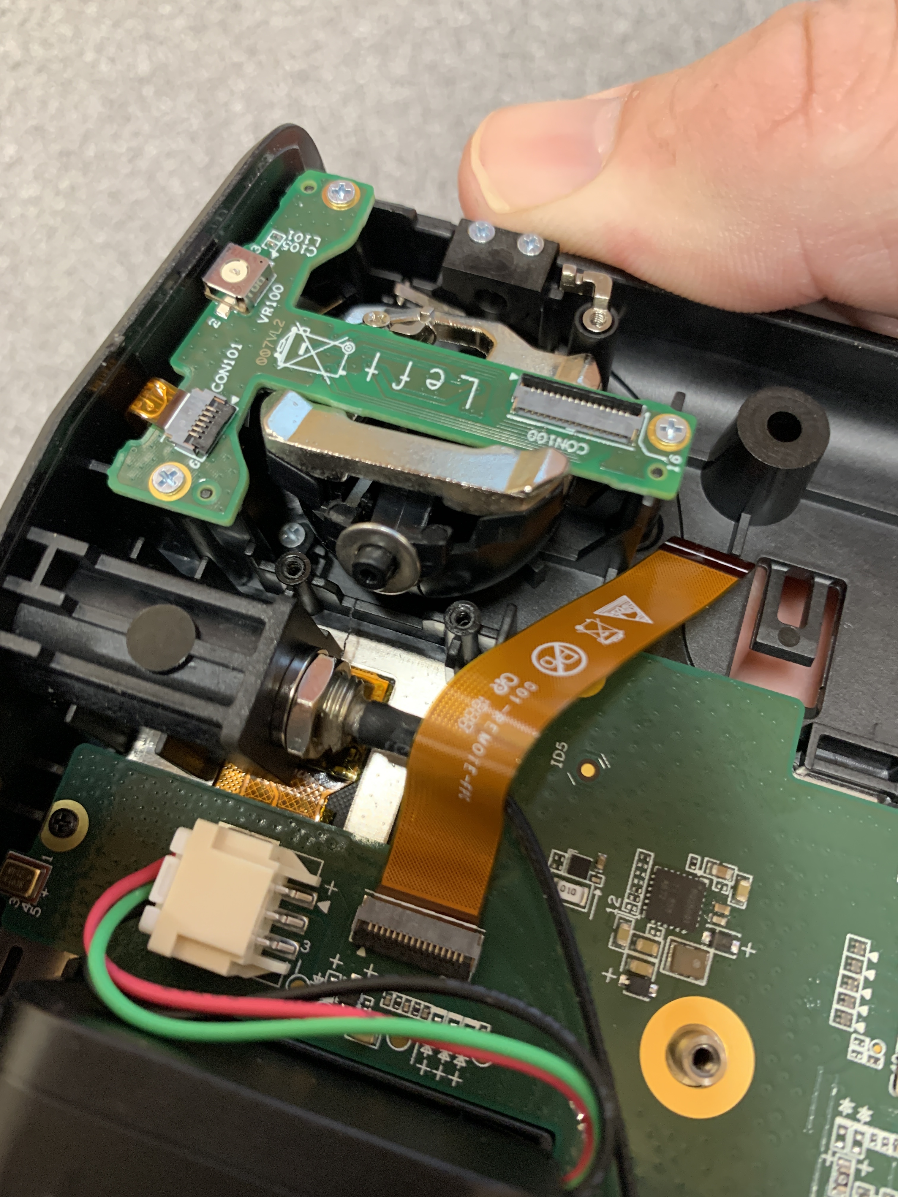
5: carefully remove the ribbon cable to the throttle gimbal board and place this safe out of the way. These are removed by lifting the small black lever at the rear of the plug and gently removing the cable.
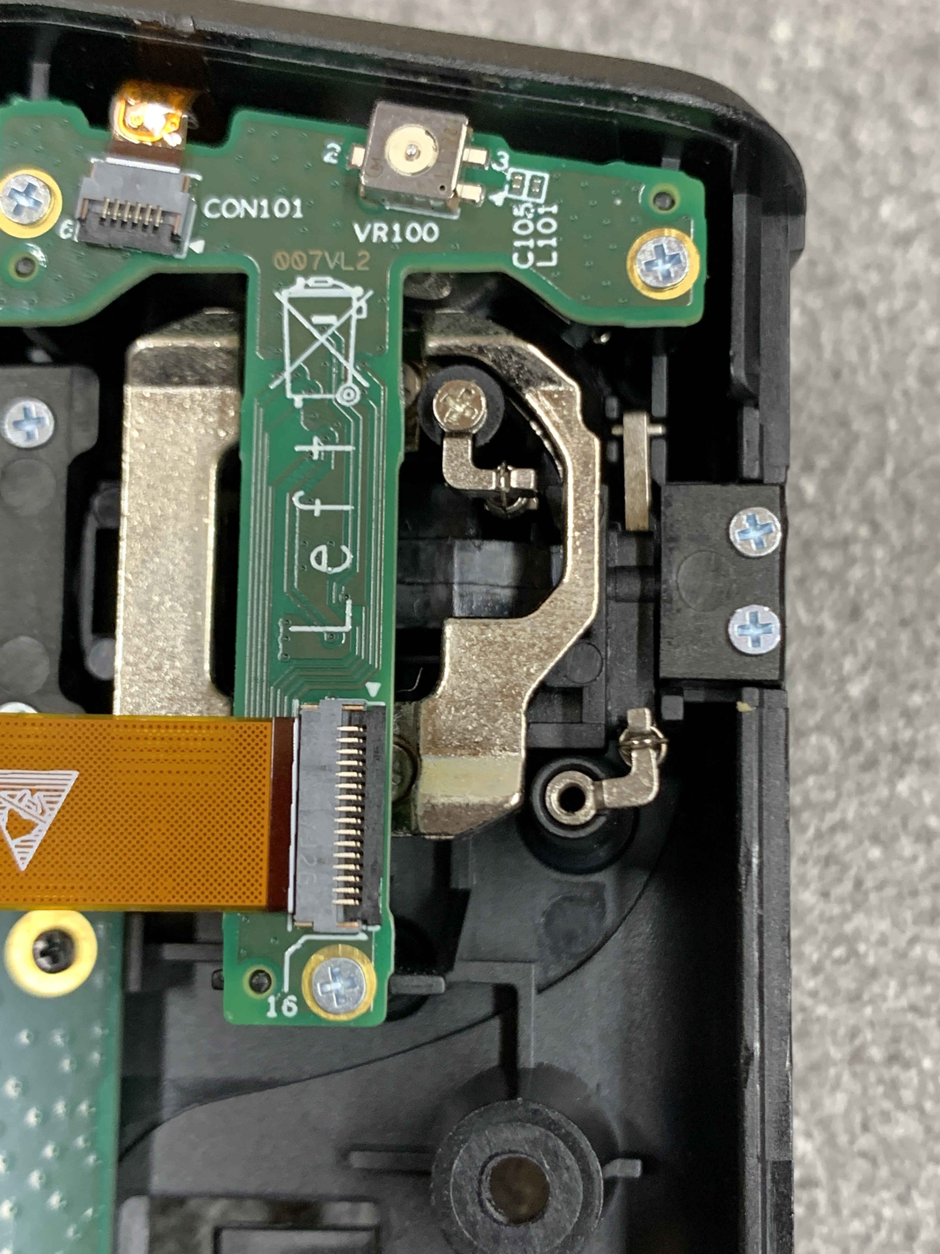
6: remove the 2 screws holding the LH Gimbal holder in place, gently then remove the bracket. This will allow the gimbal to move under the board to give you more space on the other side.
Note: there is no need to remove the Hall affect sensor board that’s located on top of the gimbal to perform this mode however if your more compatible in doing so I may be easier.
7: remove the spring from the post on the RH side and then remove it and the arm it’s attached too. This is the throttle self centring spring.
8: Refit the gimbal and new holder and re assemble not forgetting to plug the battery back in.
Recalibrate all controls.
You can download the STL files here