Hi
With the Here3 we are able to have the GPS connected to the cube via DroneCAN and listen to the GPS data in parallel over UART with our flight monitoring unit.
I’ve read that only 3.3V on the I2C activates the Here4 to communicate over UART. How can we enable an additional GPS data output on the Here4 UART?
Could you provide us with a firmware that is capable of doing so or else provide us with the necessary documents (block diagrams, schematics) so we can write the code ourselves?
@mm-dbr the firmware project running on Here4 is available here: GitHub - CubePilot/GNSSPeriph-release
As to answer your question regarding connecting to Ublox module onboard over DroneCAN, you can follow these steps to do so. Disregard firmware update part of the steps, just follow the connection part.
Thanks for the quick reply and the links, but i don’t think you’ve completely understood our issue.
Currently, the Here3 is connected over DroneCAN to the FCU and the GPS UART TX line is connected to another uC, where we can monitor the GPS data additionally. We had to configure the UART to output the GPS data over UART for this to work. Now we would like to do the same with the Here4, but since the F9P is not directly connected to the UART of the Here4 10Pin JST, we need to find some way to make the Here4 STM output the GPS data on UART as well.
From Github it looks like you pass-through the UART if the I2C line is attached and then the GPS via DroneCAN is deactivated. The simplest solution from our point of view is for you to add a configurable transmission pass-through of the TX line (not the RX to prevent interference) from the F9P module to the UART of the Here4 connector, with the DroneCAN interface still active. With this, we (and others) could still benefit from firmware upgrades as well, without internal code adaption with every update.
The other option would be the following:
We would use the M4 processor to handle the UART-forwarding to the UART output on the connector. Therefore we’d need a block diagram or a schematic. But we’re not that familiar with the Arducopter libraries that you’ve linked in your code. And the baud rate between the F9P and your STM H7 is very fast and this could complicate things for our solution as well.
Is this feasible and if so, can you provide us the documents? We could also set up an NDA if necessary.
@mm-dbr Usually the requirement for Here4 operation when using Serial and I2C is to be backwards compatible with old mechanism. This also requires us to make sure that Here4 main firmware gets out of the loop to manage ublox configuration in this case. Otherwise the FC connected over Serial will end up fighting Here4 main firmware. I2C is the easiest way to detect if the FC is using this interface and hence was used for this switch.
Your requirements are not usual way the Here4 will be used but can be fulfilled with minor changes to the code. I will see if I can find time to add this support.
If you want to have a go at it I would welcome your PR as well. Basically you can add code to this file GNSSPeriph-release/AP_Periph/serial_tunnel.cpp at release · CubePilot/GNSSPeriph-release · GitHub.
Currently it only sets up serial monitor when it receives Tunnel packet. You will need to add a parameter to setup this up inside the send_serial_monitor_data method when enabled and push the data buffered by monitor loop over to the serial port you want. You can also add option to set the serial port to the same baud rate as the F9P serial port or use parameter to set it to a value you want.
1 Like
Hi Siddarth
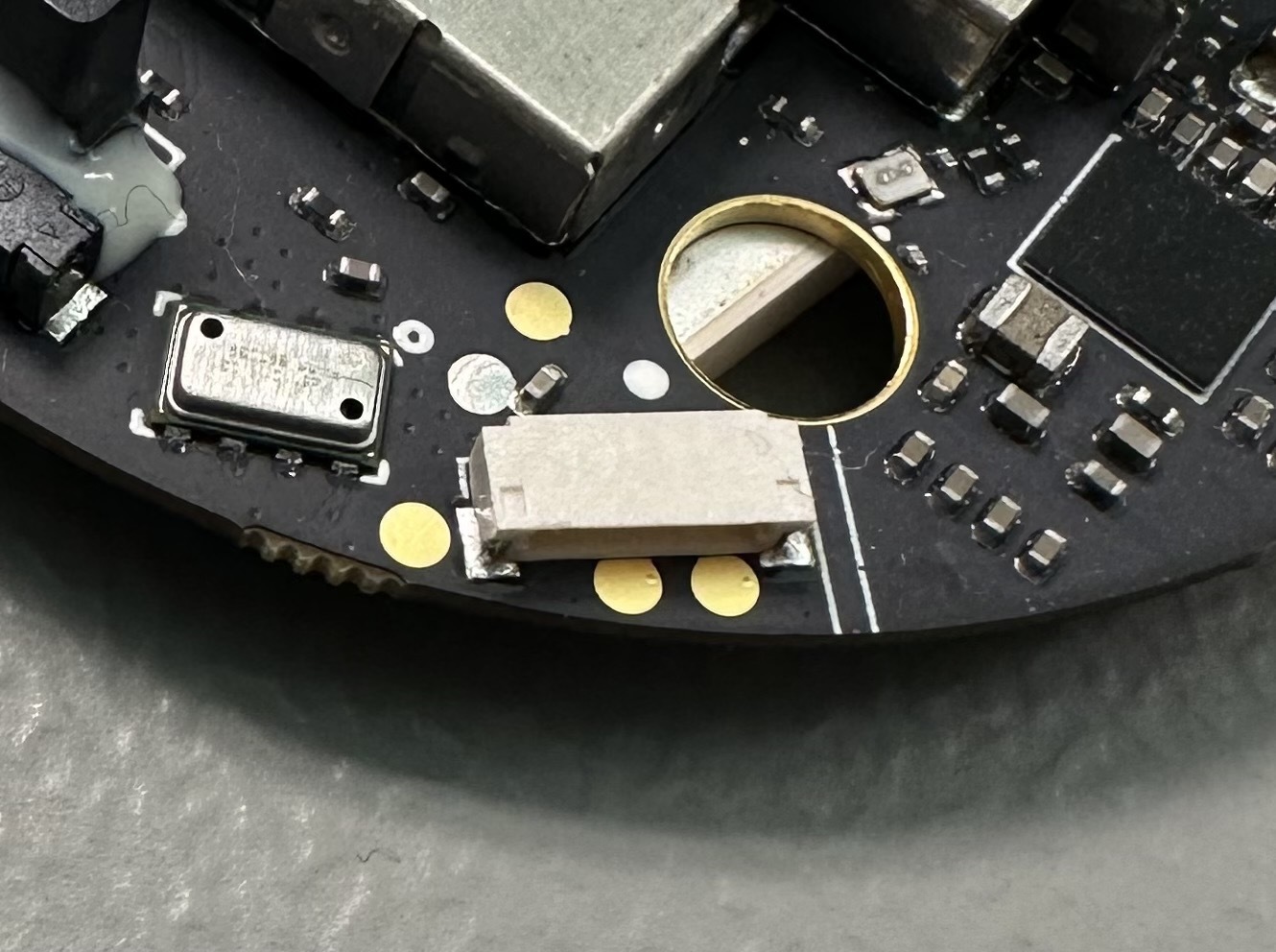
Our software team is currently looking into this issue and is wondering, if there is an SWD or JTAG connection available on the Here4, which we can use for programming?
Yes. The tiny connector on PCB you’ll see is for swd. You’ll have to open case.
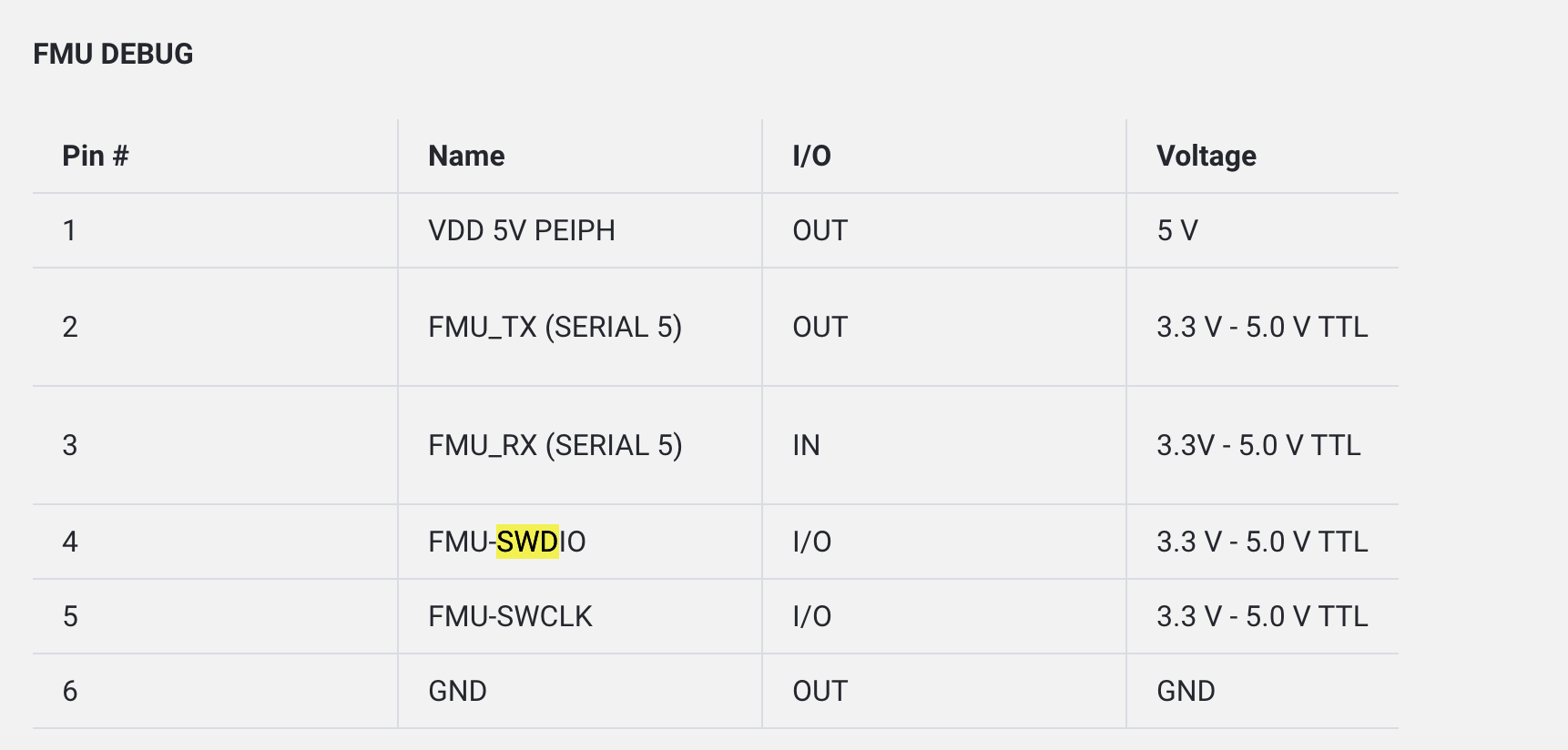
Yes that is the correct pin out. It’s been same for a long time.
Best way would be to modify GNSSPeriph-release project to do what you need.
Hi Siddharth,
thanks for your support and your patience with this thread ![]()
I am Dominik’s software colleague who is supposed to find an optimal long-term solution for the mentioned feature (sniffing HERE4 via GPS UARTx_Tx on 10Pin JST, in parallel with Cube FCU connected via CAN).
As Dominik explained already, our FMU (flight monitor unit) MCU was working previously with two HERE3 modules (pcb label “CAN HERE REV2”, with STM32F302 DroneCAN MCU) connected via two CANx to the FCU. With SW1 in “CAN” position, we are still able to get the HERE3 UART_Tx output on 10Pin JST, for sniffing the UBX_NAV_PVT packets coming at known (FCU configured) baud-rate.
Moreover, only this single packet type is parsed by FMU, the rest HERE traffic was ignored by FMU.
We have no possibility in existing FMU design to sniff the two CAN buses from both HERE4…
My understanding is that in HERE3 the same UART between the uBlox / STM32F302 was wired in parallel to 10Pin JST, thus the data on UART_Tx line is available “at no CPU cost” (no routing is required on STM32F302 side). And as long as no uBlox UART_Rx was wired externally on 10-pin connector, there is no risk of data collision (external UART host vs. the internal STM32F302 bridge).
Ideally, it would be nice for us to have the same possibility (F9P UART_Tx streamed to 10Pin JST connector) also in HERE4, but looks the STM32H7 has different UARTx to F9P and UARTy on 10Pin JST. Thus, H7 firmware routing is required (we are only interested in “F9P to 10Pin JST” side).
Moreover, as the new features on F9P might required ever increasing UART data rates, I am not sure if such “bit-wise routing” solution (in HW or SW) would be acceptable for FMU sniffer via ca. 30cm serial cable…
I cannot judge how many other customers will require the same feature (possibly those making new electronics design for HERE4 integration, would rather consider their FMU with CAN bus sniffers?).
Before I start experimenting with HERE4 firmware modifications (in background), I would like to sum up possible alternatives, and would appreciate your feedback, few answers / info.
The optimal solution would be - to add the feature once, i.e. that I do not need to merge the fix periodically if newer HERE4 firmware appears. On the other hand, if the feature is rarely reused by other customers - to avoid STM32H7 run-time overhead (e.g. activate UART routing once from FCU via option, stored in HERE4 settings).
The alternatives:
a) in case some short-term HERE4 pcb redesign is planned - just add a switch / solder jumper which connects the F9P UART_Tx to the 10Pin JST.
Very improbable option, but 0-CPU extra overhead.
b) if I understood correctly, the STM32H75x CM4 CPU is currently not used at all.
Activating the generic “bit-wise repeater” routing (UARTy_Tx on 10-pin connector follows the UARTx_Rx from F9P - like done in original FW, in case the DroneCAN disabled via I2C IO) - by CM4.
In particular, CM4 could be initialized (e.g. code from 1KB RAM) from customized Bootloader.
Would ideally allow the HERE4 CM7 original binaries FW updates - without future code patching, - provided the CM7 startup does not “suppress” the CM4 routing.
The benefits also: this works with any future F9P UART baud-rates, etc. The “bit-level repeater” of course consumes factor 10 more CPU cycles, but this is done by CM4 and does not affect CM7 performance!
As variation to this option: CM4 FW is present in DroneCAN MCU application image but is enabled by CM7 only in case some config option (from FCU) was enabled.
c) regular patching of the HERE4 source (at application F9P parser, or UART driver level) to forward the F9P UART Rx packet to 10-pin connector (one direction). Here again the 2 options are feasible:
- generic routing of whole traffic (at same baudrate as F9P UART) - meaningful for flexible reuse by other customers as well.
Could be done byte-wise from F9P Rx IRQ, or for complete received UBX message (or each fixed N bytes Rx / after timeout - whichever happens first)
d) - only specific single packet type UBX_NAV_PVT is routed: when whole Rx packet parsed, it could be copied into dedicated RAM buffer, and start sending by DMA or IRQ of that UARTy_Tx.
Makes sense if no interest to merge this (our company specific?) patch into the git main stream with runtime (or compile-time) configurable option.
This alternative also allows to send the only required data at lower / fixed UART baudrate (say 115kbps) - regardless of higher rate used on very short F9P / STM32H7 path, and to reduce our FMU loading for parsing the not used other GNSS packet types (which may essentially increase / vary with future F9P / DroneCAN firmware versions or enabled features like moving baseline…)
Applying this patch in average 1-2 times per year to a newer HERE4 code base would be acceptable option for me (considering the above-mentioned system benefits) - provided we’d verify / review once that patch does not introduce the HERE4 CM7 overhead, which could affect the original DroneCAN functionality, - also in the future HERE4 FW.
As I am not deeply familiar with Ardupilot and AP_PERIPH libs code hierarchy, and debugging / profiling tools, my primary concern is not how to make the F9P UART stream routing at all, - but to verify that adding this feature does not affect dramatically the DroneCAN original FW performance / latency. Once looked at ChibiOS, I remember its integrated original UART drivers (all 3 types) did not support DMA, etc.
The questions:
-
I would appreciate the HERE4 schematic or at least block-diagram (which STM32H7 UARTn is used for what, etc.). Even with open-source SW it is not obvious.
Please send me a PM if you do not want to share on this board. -
is the FMU_TX/RX (SERIAL5) on 6-pin “FMU DEBUG” connector, as posted by Angel_Riya, wired to some HERE4 STM32H7 serial, or was that only standard pins assignment from Cube FCU pcb, etc.?
-
some useful links to HERE4 debugging / profiling techniques you usually apply. (I tried briefly to open the prebuilt HERE4 debug image with Segger Ozone on Ubuntu, but other hints are welcome!).
-
estimation / prediction on actually used / future F9P UART data throughput depending on supported features would be great.
I see no problem when internal onboard UART between F9P and STM32H7 DroneCAN is running at 230kbps … 921kbps, and the path to FCU is not a problem as some 30cm differential CAN signal.
But if enabling the routing at same as F9P baud-rate from HERE4 connector via ca. 30cm serial line, this could lead to frequent packets loss in noisy UAS in the future…
For that reason, if we cannot guarantee keeping configurable (via FCU settings) HERE4 DroneCAN UART rate in 115…230kbps range to F9P in the future FW (say >= 460kbps will become a standard due to increased traffic rates with RTK / L5 band / moving baseline…) - I see only the proprietary option (d) as future-safe solution (with TODO of switching our next electronics redesign to the two CAN-buses FMU sniffer).
@mm-vty The feature for interfacing straight over UART is one of the features to be eventually added. The issue is mostly related to baud rate detection, it is currently not supported to detect baudrate of the connected device in ardupilot. I plan on working on that at some point. When that’s done the feature will be added.
Meanwhile if your need is simply to get GPS UART data pumped onto a different serial port you can do so by enabling and editing this bit of code: GNSSPeriph-release/AP_Periph/GPS_Rover.cpp at release · CubePilot/GNSSPeriph-release · GitHub. Instead of dumping the data onto emmc (done on HerePro) you can simply dump it onto a serial port (through hal.serial(x)->write() call). This will be a one way interface, which is probably what you want, otherwise you will have conflict between onboard configurator and your interfaced device.
Regarding the schematics: GNSSPeriph-release/Here4/hwdef.dat at release · CubePilot/GNSSPeriph-release · GitHub has enough enough information to meet those needs, further pinouts can be found here ardupilot/libraries/AP_HAL_ChibiOS/hwdef/Here4FC/hwdef.dat at master · ArduPilot/ardupilot · GitHub . Basically you have enough details between these two files to know which STM32H7 pin is connected to where.
Jlink is ok for debugging and developing. We normally use it with gdb server rather than Ozone, but ozone works too.
Hi Siddharth,
thanks a lot for your valuable feedback! I think the template with AP::gps().set_gps_raw_cb() is exactly what I need. Provided also the hal.serial(x)->write() works via DMA sending on that JST10 UART, this is all I need and my patch should not introduce the original HERE4 firmware extra latency or CPU usage. I will try sending only UBX-NAV-PVT currently used by our FMU at 115200 baud as prev. discussed (to reduce cable noise and processing on FMU side). As this looks too proprietary solution, it possibly makes no sense to merge it into the original HERE4 code base, but if you are interested - I can send you my final solution later (for review or potential merging).
Hi Siddharth,
short update / question.
-
I got serial0Driver (USART1) output on 10-pin connector pin 7 (GPS_RX).
https://docs.cubepilot.org/user-guides/here-4/here-4-manual#id-10-pin-in
If the manual describes connector from FCU peer side, this is correct one.
We just had similar “swapped Tx/Rx” issue with HERE3 against the product page description. -
I’ve just noticed that the same serial0Driver is also exposed as hal.console, initialized in constructor as unconditionally passed parameter in HAL_ChibiOS_Class.cpp. And I see the hal.console.print() and co. calls are still unconditionally present in the sources. If this would be the last message before crash (or GPS not working anyway) it is OK, but the worst case if some unrelated library periodically produces such text messages, interlaced with my routed UBX binary packets. Could you consider some configurable patch to redirect the hal.console at compilation time, etc.?
Hi Volodya,
I actually have the same issue, that I want the GPS data on the drone onto another microcontroller. I’m working on a project where we mount an RFID reader on the drone and I want to send the RFID data + RTK precision GPS data over a separate wifi connection to a windows server. Would be ugly to have a separate GPS receiver on the drone. We have no experience in compiling Here 4 software. Do you think you could share your firmware and give a hint how to get it working? Looks as if you are not alone with the wish to spy the GPS data ![]()
Hi Klaus,
as discussed above, my patch is our product requirements specific, i.e. I am routing ONLY one packet type UBX-NAV-PVT onto the JST-10 connector via UART at 115200 8N1. Normally it comes at 5Hz. If this is exactly what you need, just try to reflash attached *.apj file. In MissionPlanner GUI you will see my “UBX_NAV_PVT router” can_printf() messages each 10 seconds. If this is the case - try to get HERE4 USART1 data on JST10 pin 7 at 115200 baud.
Otherwise, if your requirements are similar but not the same, attached are few sources with my actual patch. You may use it as starting point to extend with your needs.
- in /here4-fw/Here4/hwdef.dat: at the very end of file - to activate my patch when rebuilding the sources
define UBX_NAV_PVT_ROUTER - added the desired implementation - new source
/here4-fw/AP_Periph/ubx_router.cpp - integration of feature activation - min. changes in
/here4-fw/AP_Periph/AP_Periph.cpp
all trackable via conditional code
#ifdef UBX_NAV_PVT_ROUTER
How to install the environment / rebuild HERE4 from sources - you will find the links on top of this page.
Hope this helps you!
Here4_Patch.zip (188.8 KB)